background image

61

Shock Assembly and Bleed

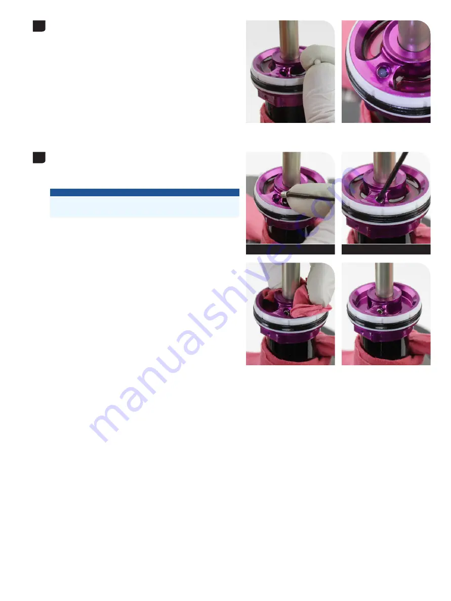
Allow oil and air bubbles to escape from the bleed port in the seal 

Allow oil and air bubbles to escape from the bleed port in the seal 

head / air piston. 

head / air piston. 
Insert a NEW nylon compression ball into the bleed port. Allow it to 

Insert a NEW nylon compression ball into the bleed port. Allow it to 

settle into place below the threads.

settle into place below the threads.

Install the bleed screw into the bleed port and thread it in until you feel 

Install the bleed screw into the bleed port and thread it in until you feel 

it contact the nylon compression ball, then tighten the bleed screw an 

it contact the nylon compression ball, then tighten the bleed screw an 

additional ½ turn.

additional ½ turn.
Clean the oil from the seal head.

Clean the oil from the seal head.

NOTICE

Overtightening the bleed screw can damage the nylon compression 

ball. If the nylon compression ball is damaged, it must be replaced.

2 mm

2 mm

Summary of Contents for DELUXE 2023

Page 1: ...SERVICE MANUAL GEN 0000000007153 Rev A 2022 SRAM LLC 2023 DELUXE...

Page 2: ...NOT APPLY TO YOU LIMITATIONS OF WARRANTY This warranty does not apply to products that have been incorrectly installed adjusted and or maintained according to the respective SRAM user manual The SRAM...

Page 3: ...SAFETY FIRST We care about YOU Please always wear your safety glasses and protective gloves when servicing RockShox products Protect yourself Wear your safety gear...

Page 4: ...EARING REMOVAL SHAFT EYELET 19 BEARING INSTALLATION SHAFT EYELET 22 DAMPER BODY BEARING EYELET ASSEMBLY REPLACEMENT 26 DELUXE SERVICE 27 PARTS TOOLS AND SUPPLIES 27 50 200 HOUR SERVICE AIR CAN SERVICE...

Page 5: ...an the part with Clean the part with RockShox Suspension Cleaner or isopropyl alcohol and isopropyl alcohol and a clean lint free shop towel For hard to reach places e g upper tube lower a clean lint...

Page 6: ...oduct version associated with the production model year Product details can be used to identify spare parts service kit and lubricant compatibility Model Code example RS DLX SEL C1 RS Product Type Rea...

Page 7: ...stores suspension performance R e c o r d Y o u r S e t t i n g s Use the table below to record your shock settings to return your shock to its pre service settings Record your service date to track s...

Page 8: ...Bearing press tool 22 mm OD x 10 mm ID bearing eyelet only Bearing punch 1 16 1 5 mm OD seal head compression ball removal 1 8 3 mm OD eyelet bearing removal Bench vise with soft jaws Crowfoot socket...

Page 9: ...eed screw Nylon compression ball Seal head air piston Negative Volume Token Damper piston Compression rod Lift plate Travel reducer Eyelet bushing standard eyelet Air cap Air valve Threshold lever ped...

Page 10: ...y Eyelet bearing x2 Lock piston Washer Washer Bottomout bumper Damper shaft Bleed screw Nylon compression ball Seal head air piston Negative Volume Token Damper piston Piston nut Compression rod Deten...

Page 11: ...r can progressive Air can linear Washer Washer Bottomout bumper Damper shaft Bleed screw Nylon compression ball Seal head air piston Negative Volume Token Damper piston Piston nut Travel reducer Eyele...

Page 12: ...nch vise with soft jaws M o u n t i n g H a r d w a r e R e m o v a l NOTICE To prevent damage to the shock use aluminium soft jaws and position the eyelet in the vise so that the adjustment knobs are...

Page 13: ...on the end spacer on the end spacer Hold the pin catcher secure with a 13 mm open end or adjustable Hold the pin catcher secure with a 13 mm open end or adjustable wrench wrench NOTICE Do not scratch...

Page 14: ...long the rod until it pushes the pin completely out of the eyelet and stops against the pushes the pin completely out of the eyelet and stops against the eyelet eyelet Unthread the catcher from the th...

Page 15: ...3 mm wrench Hold the catcher secure with a 13 mm wrench Use a second 13 mm wrench to thread the push pin along the rod until Use a second 13 mm wrench to thread the push pin along the rod until the pu...

Page 16: ...16 Eyelet Bushing Removal Clean the eyelet Clean the eyelet 4...

Page 17: ...haft eyelet until the bushing rests Insert the threaded rod through the shaft eyelet until the bushing rests against the eyelet against the eyelet Thread the large open end of the catcher onto the rod...

Page 18: ...rod and push Unthread and remove the catcher Remove the threaded rod and push pin tool pin tool Wipe the grease from the eyelet and bushing Wipe the grease from the eyelet and bushing To continue Stan...

Page 19: ...e shop towels Nitrile gloves Safety glasses Lubricants and Fluids RockShox Suspension Cleaner or isopropyl alcohol RockShox Dynamic Seal Grease Common Tools Bearing press tool 22 mm OD x 10 mm ID bear...

Page 20: ...te of the air valve first the air valve first Position the punch through one bearing and against the back of the Position the punch through one bearing and against the back of the opposite bearing Pre...

Page 21: ...l process Turn the shock over and repeat the bearing removal process NOTICE Shaft Eyelet bearing eyelet Do not damage the air valve when tapping out the bearing Clean the bearing bores Clean the beari...

Page 22: ...bearing bore then clamp the eyelet and Install a new bearing into one bearing bore then clamp the eyelet and bearing into a vise with soft jaws Press the bearing into the bearing bearing into a vise w...

Page 23: ...edge press tool is centered and is not overlapping the bearing edge Press the bearing into the bearing bore until it stops Press the bearing into the bearing bore until it stops Remove the shock and...

Page 24: ...then install a new bearing into the other bearing bore other bearing bore Clamp the eyelet and bearing into a vise with soft jaws then press the Clamp the eyelet and bearing into a vise with soft jaws...

Page 25: ...Do not overtighten the bearing Overtightening can damage the bearing and cause it to malfunction To prevent damage to the bearing make sure that the bearing press tool contacts both the inner and oute...

Page 26: ...ng dust covers Loosen the bearing eyelet bolts and remove the Loosen the bearing eyelet bolts and remove the damper body bearing eyelet assembly from the damper body from the damper body Install the n...

Page 27: ...liers Open end wrench 13 x2 24 29 34 54 mm Pick metallic Pick non metallic Schrader valve tool Socket 12 mm Socket wrench Rubber strap wrench Torque wrench NOTICE Use only 2023 C1 Deluxe spare parts a...

Page 28: ...cks Record this number Record this number to to assist you with post service set up assist you with post service set up Ultimate RCT Select RT Select RL Ultimate RCT Select RT Select RL Rotate the Thr...

Page 29: ...ir is removed from both chambers Quickly releasing the air can trap air in the negative chamber and cause the air can to forcefully eject from the shock upon disassembly Use a Schrader valve tool to r...

Page 30: ...ir can Firmly turn the wrench counter clockwise to unthread the air can wrench counter clockwise to unthread the air can Once it is completely unthreaded firmly pull the air can toward the end Once it...

Page 31: ...TION EYE HAZARD Vacuum pressure will increase as you pull the air can along the damper body and will suddenly release when the air can is pulled off the air piston Wear safety glasses Remove the Count...

Page 32: ...the specification a 2023 C1 Deluxe rear shock may include 0 4 Bottomless Tokens 0 1 negative volume Tokens include 0 4 Bottomless Tokens 0 1 negative volume Tokens Some Deluxe rear shocks include a b...

Page 33: ...n Snap the negative volume Token onto the seal head air piston Token onto the seal head air piston Remove Negative Volume Token Remove Negative Volume Token Carefully pry up both sides of the negative...

Page 34: ...ing located below the shaft eyelet threads Clean the inside of the eyelet Clean the inside of the eyelet Apply grease to a new o ring and install it into the eyelet Apply grease to a new o ring and in...

Page 35: ...an the inside and outside of the air can Clean the inside and outside of the air can Inspect the inside surface of the air can for scratches dents or Inspect the inside surface of the air can for scra...

Page 36: ...ting one end into the deepest groove in the air can then push the remainder of the ring into the groove in the air can then push the remainder of the ring into the groove groove Install the new wiper...

Page 37: ...he air can and eyelet threads with a shop towel Apply grease to a new o ring and install it onto the air can Apply grease to a new o ring and install it onto the air can Set the air can aside Set the...

Page 38: ...head air piston Clean the seal head air piston NOTICE Do not remove or replace the seal head backup ring The fixed seal head backup ring is sized at the factory and does not require service Apply gre...

Page 39: ...further service service CAUTION EYE HAZARD Verify all pressure is removed from the shock before proceeding Failure to do so can cause the damper body to separate from the shaft eyelet at a high veloci...

Page 40: ...with your hand to prevent the wrench from slipping and scratching the damper body Unthread the seal head air piston one scratching the damper body Unthread the seal head air piston one full turn full...

Page 41: ...e the damper body vertically onto a shop towel and allow the excess oil and cleaner to drain excess oil and cleaner to drain Inspect the inside and outside surfaces of the damper body for Inspect the...

Page 42: ...seal head air piston assembly above the vise block Clamp the damper shaft into the 10 mm vise block slot tight enough so Clamp the damper shaft into the 10 mm vise block slot tight enough so it does n...

Page 43: ...ression needle and lock piston assembly from the damper piston and damper shaft Set the piston assembly from the damper piston and damper shaft Set the compression needle assembly aside compression ne...

Page 44: ...s is normal shims may stick to the underside of the lock piston This is normal NOTICE Apply pressure to the Lock Piston Tool when removing the lock piston to prevent the tool from slipping on the pist...

Page 45: ...Loosen the piston nut Do not remove it completely from the piston assembly to avoid separating the remove it completely from the piston assembly to avoid separating the parts parts 7 12 mm Ultimate R...

Page 46: ...shaft and slide the piston and shim stacks stacks from the damper shaft and slide the piston and shim stacks onto the pick to keep them all together in the correct order onto the pick to keep them all...

Page 47: ...seal head air piston assembly from the damper shaft Remove the bottom out bumper and discard it Remove the bottom out bumper and discard it Clean the damper shaft Clean the damper shaft Install a new...

Page 48: ...install it Apply grease to a new internal o ring and install it Remove the inner o ring from the underside of the seal head air Remove the inner o ring from the underside of the seal head air piston a...

Page 49: ...ugh the bleed port The nylon compression ball will be deformed and cannot be reused The nylon compression ball will be deformed and cannot be reused Discard the compression ball Discard the compressio...

Page 50: ...he shaft eyelet threads Remove the o ring located below the shaft eyelet threads Clean the inside of the eyelet Clean the inside of the eyelet Apply grease to a new o ring and install it into the eyel...

Page 51: ...vise blocks grease so the damper shaft does not spin in the vise blocks Clamp the damper shaft in the vise blocks with the seal head air Clamp the damper shaft in the vise blocks with the seal head ai...

Page 52: ...e damper shaft Insert the pick into the damper shaft and install the piston assembly Insert the pick into the damper shaft and install the piston assembly onto the damper shaft onto the damper shaft S...

Page 53: ...he stepped side down facing the shims and piston with the stepped side down facing the shims and piston Thread the nut onto the damper shaft by hand when all shims are Thread the nut onto the damper s...

Page 54: ...te RCT In the same order as removed install the lock shim In the same order as removed install the lock shim stack onto the piston bolt stack onto the piston bolt Use a second pick to guide the shims...

Page 55: ...and Apply even downward pressure to the Deluxe RCT NUDE Lock Piston Apply even downward pressure to the Deluxe RCT NUDE Lock Piston Tool when installing the lock piston to prevent the tool from slippi...

Page 56: ...press the nut Align the guide pin with the hole in the lift plate then press the nut down to lock the compression rod assembly into place down to lock the compression rod assembly into place NOTICE D...

Page 57: ...r valve adapter and pump from the damper body Spray RockShox Suspension Cleaner inside and outside of the damper Spray RockShox Suspension Cleaner inside and outside of the damper body body Place the...

Page 58: ...able below printed on the damper body as specified in the table below Do not push the IFP in too far If it is pushed into the damper body Do not push the IFP in too far If it is pushed into the damper...

Page 59: ...ghten the vise tight enough to crush the damper body The RockShox Rear Shock Body Vise Block holds the IFP in place Failure to use the vise block when clamping the damper body into the vise may result...

Page 60: ...Do not hold the eyelet while installing the seal head air piston and Do not hold the eyelet while installing the seal head air piston and damper piston The seal head air piston may move and cause too...

Page 61: ...le into place below the threads Install the bleed screw into the bleed port and thread it in until you feel Install the bleed screw into the bleed port and thread it in until you feel it contact the n...

Page 62: ...n pressurized remove the air valve adapter tool from the air valve port before removing it from the shock adapter tool from the air valve port before removing it from the shock pump pump NOTICE Separa...

Page 63: ...r Measure assembly onto the damper body Slide it to Install the Counter Measure assembly onto the damper body Slide it to the seal head air piston the seal head air piston Apply grease to the seal hea...

Page 64: ...op when damper body protrudes through the air can wiper seal Stop when there is a gap between the air can and the shaft eyelet assembly there is a gap between the air can and the shaft eyelet assembly...

Page 65: ...can decal While holding the strap wrench firmly to stabilize the shock tighten the While holding the strap wrench firmly to stabilize the shock tighten the eyelet assembly into the air can Use the ap...

Page 66: ...hing pin If this works you have completed mounting hardware and bushing service If you are unable to install your standard eyelet mounting hardware using your fingers use the RockShox Rear Shock 1 2 x...

Page 67: ...let bushing it pushes the bushing pin into the shock eyelet bushing Use one spacer to check the pin position The pin should be centered Use one spacer to check the pin position The pin should be cente...

Page 68: ...st onto each end of the bushing pin pin The bushing pin should be centered in the eyelet and no portion of The bushing pin should be centered in the eyelet and no portion of either end should protrude...

Page 69: ...all the bearing dust covers when the shock is installed back onto Install the bearing dust covers when the shock is installed back onto the bicycle the bicycle S h o c k I n s t a l l a t i o n a n d...

Page 70: ...Karoo Komfy LINK Lyrik MatchMaker Maxle Maxle 360 Maxle DH Maxle Lite Maxle Lite DH Maxle Stealth Maxle Ultimate Micro Gear System Mini Block Mini Cluster Monarch Monarch Plus Motion Control Motion Co...

Page 71: ...1598 8 Chung Shan Road Shen Kang Hsiang Taichung City Taiwan R O C WORLD HEADQUARTERS SRAM LLC 1000 W Fulton Market 4th Floor Chicago Illinois 60607 U S A EUROPEAN HEADQUARTERS SRAM Europe Paasbosweg...

Reviews: