ROCKET LAB PSC MOTORIZED Lightband MKII Operating Procedure Download Page 66

Copyright PSC 

2000781K MkII MLB Operating Procedure 

Page 66 of 68


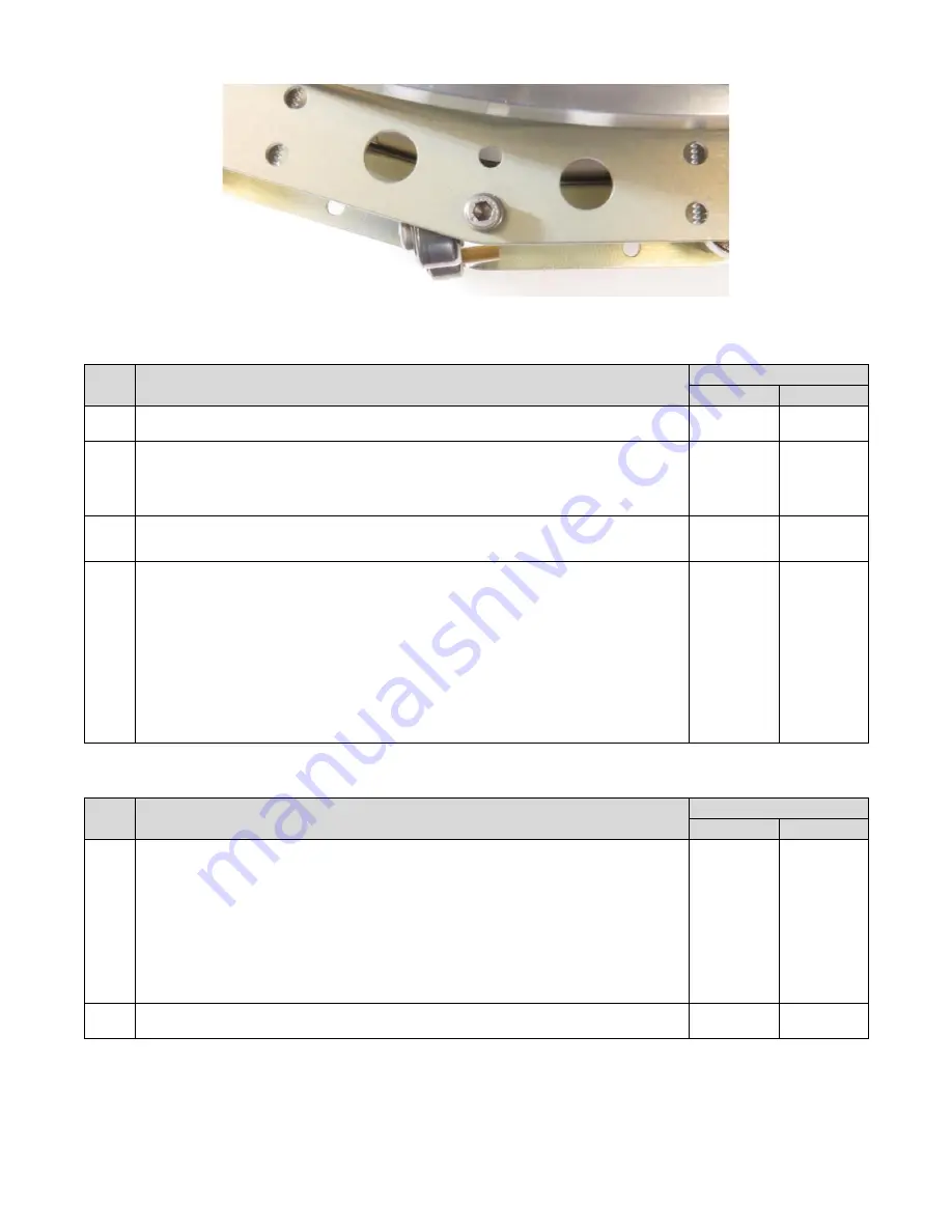
Figure 17-3: Visually aligned LCT pair 


17.3  Mating the Lightband 

Step 

Procedure 

Date & Initials 

Tech. 

QA 

17.3.1   

Upper and Lower Rings shall be aligned per Step 7.1.11. 


17.3.2   

Prepare cable tie tool 

1.  Disable cut-off feature (if present). 
2.  Ensure force setting does not exceed cable tie break strength. If using 

referenced tool, 

set to ‘8’. 


17.3.3   

Place one cable tie around each LCT pair and pull until just taut. Do not 
compress the Separation Springs. 


17.3.4   

Measure the distance between Upper and Lower Ring flanges (A and B in  
Figure 17-1) next to each LCT and record in Table 17-1. For reference the 
nominal uncompressed distance is 2.13 inch for the dimension shown in Figure 
7-7.
  
 
Lightly tighten each cable tie until the flange distance measures 2.00 to 2.05 
inch at every LCT (1). 
 
Note: Failure to evenly compress the Lightband increases probability of 
breaking cable ties. 


1)  If using a combination of weight and LCTs to compress the Lightband, the initial flange distance will be less 

than stated above. Record the minimum initial reading and adjust all LCTs until they are within 0.05 inch. 


Step 

Procedure 

Date & Initials 

Tech. 

QA 

17.3.5   

To compress the Lightband tighten the cable ties in maximum increments of 
0.05 inch. Work around the Lightband and record all measurements in Table 
17-1 a
fter each round of adjustments. The flange distance at all LCTs shall 
agree within 0.05 inch prior to compressing further. 
 
If a cable tie is over-tightened or breaks, remove and replace the cable tie. 
 
Repeat this iterative process until the flange distance at every LCT complies 
with the pre-Stow distance in Figure 7-7. 


17.3.6   

Proceed to section 8 to Stow the Lightband. 

-----N/A-----  -----N/A----- 

Summary of Contents for PSC MOTORIZED Lightband MKII

Page 1: ...Copyright PSC 2000781K MkII MLB Operating Procedure Page 1 of 68 MOTORIZED Lightband MKII Operating Procedure 2000781K spacesystems rocketlabusa com rocketlabusa com...

Page 2: ...7 13 HORIZONTAL INTEGRATION OPTIONAL 58 14 LIGHTBAND ELECTRICAL SCHEMATICS 60 15 RECOMMENDED SUPPORT EQUIPMENT 61 16 SETUP PICTURES 62 17 CAUTION UNINTENDED ELECTRICAL PATHS 63 18 LCT PROCEDURE 64 Do...

Page 3: ...ding added reminder for Sep Connector and Switch attachment 12 Section 7 incorporated prior section 12 Preparing to Compress 13 Section 7 used to be a part of the Stow section 14 Step 7 1 4 increased...

Page 4: ...vehicle MBA Motor Bracket Assembly a subassembly of the MLB Mk II Mark II a model designation of the Motorized Lightband MLB Motorized Lightband used interchangeably with Lightband mtr Motor NC Norma...

Page 5: ...oove Typically the Lower Ring is attached to the launch vehicle LV and the Upper Ring is attached to the space vehicle SV The electrical interface to operate the Lightband is a DB 9 socket connector o...

Page 6: ...Copyright PSC 2000781K MkII MLB Operating Procedure Page 6 of 68 Figure 2 1 MLB15 000 24 Stowed Figure 2 2 MLB15 000 24 Deployed also referred to as separated...

Page 7: ...Copyright PSC 2000781K MkII MLB Operating Procedure Page 7 of 68 Figure 2 3 Motor Bracket Assembly internal view Figure 2 4 Motor Bracket Assembly external view...

Page 8: ...Copyright PSC 2000781K MkII MLB Operating Procedure Page 8 of 68 Figure 2 5 Motor Bracket Assembly components Stowed Figure 2 6 Motor Bracket Assembly operations...

Page 9: ...er all electrical paths and Lightband switch states shall be considered See section 16 Table 2 3 Mechanical attachment section 6 Qty Item Make Model Typically Used by PSC 1 Adjoining structure for Upp...

Page 10: ...card and reader 2 Current probe for oscilloscope 0 05 to 4 0 A range Tektronix A622 1 Adjustable timer relay with trigger 0 5 to 1 5 s with 0 1 s or finer increments Macromatic TD 78122 1 Trigger swit...

Page 11: ...eparated from the Lower Ring after every Deployment A Stow operation shall not be attempted without first inspecting the Lightband 9 Both motors shall always be powered when operating the Lightband 10...

Page 12: ...Do not grab the Separation Springs or use them to rotate the Lower Ring See Figure 5 5 7 Do not touch the Leaf Retaining Cord This is especially applicable when attaching the Lower Ring to adjoining...

Page 13: ...ocedure Page 13 of 68 Figure 5 3 Do not allow the motors to contact the table or any other objects Figure 5 4 Do not touch the gear cover Figure 5 5 Do not touch the Separation Springs Figure 5 6 Ensu...

Page 14: ...t touch spring plungers or allow them to contact anything Figure 5 8 Do not allow Upper Ring accessories to contact anything Safely handle the Lightband by grabbing the flanges on the Lower Ring and U...

Page 15: ...____________________________ Required Flatness in _________________ Measured Flatness in _________________ 1 Measured Flatness is the final assembled flatness not the flatness of the individual part A...

Page 16: ...through mounting holes It is often easier to place the washer on the Lower Ring prior to inserting the screw Tighten fasteners until hand tight See Figure 6 2 Figure 6 4 Then skip to step 6 1 10 6 1 9...

Page 17: ...ng Procedure Page 17 of 68 Figure 6 2 Inserting a SHC screw between Leaves on Lower Ring Figure 6 3 SHC screw and washer inserted between Leaves on elevated Lower Ring Figure 6 4 Separated Lightband h...

Page 18: ...the Lower and Upper Rings complies with PSC document 2000785 MkII MLB User Manual Measurement frequency shall be sufficient to ensure minimum and maximum diameters are determined See note 3 and Figure...

Page 19: ...surements N A 7 1 3 Inspect the Lightband to verify 1 It is visually free from damage 2 All Hinged Leaves are properly latched over the Retaining Ring See Figure 7 1 for proper orientation 3 The Leaf...

Page 20: ...2 Then while maintaining force on the Sliding Tube use a 7 64 inch hex key to rotate the ball screw clockwise as shown in Figure 7 3 The Ball screw should rotate smoothly with very low running torque...

Page 21: ...loading a mass a compression clamp fixture etc An isolation system if attached to the Lightband can be included in this stiffness calculation See Figure 7 5 This compliance ensures the Lightband is ab...

Page 22: ...r Figure 7 6 ensure 1 Cutout in Upper Ring aligns over Motor Bracket Assembly on Lower Ring 2 All Separation Connector Switch cutouts align 3 All Separation Spring tips protrude through appropriate ho...

Page 23: ...force gradually and verify all Hinged Leaves rotate inside the Upper Ring as it compresses Stop once the minimum force is applied 7 1 14 Once the minimum compressive force has been applied verify the...

Page 24: ...t portion of Stow Test Circuit 1 per Figure 8 1 8 1 3 Excessively long harnesses and or thin wires have significant resistance which will reduce the voltage at the motors Verify the resistance between...

Page 25: ...Copyright PSC 2000781K MkII MLB Operating Procedure Page 25 of 68 Figure 8 1 Stow test circuit 1...

Page 26: ...will capture entire duration recommend 250 ms div 8 Horizontal trigger position recommend 1 div from left of screen 9 Vertical trigger level and channel recommend Ch 1 set to 2 V 8 1 9 Perform the fo...

Page 27: ...of 68 8 2 Stow Test Circuit 2 Intermediate State Step Procedure Date Initials Tech QA 8 2 1 Set up the Test Circuit Intermediate portion of Stow Test Circuit 2 per Figure 8 2 and connect to the Stow P...

Page 28: ...for Channels 1 3 4 3 Measured current values are approximately 1 10th of applied voltage for Channels 2 4 4 4 Timer relay applies power per step 8 1 7 4 5 Data saves and is readable on a computer 5 If...

Page 29: ...ge 29 of 68 8 3 Stow Test Circuit 3 Stowed State Step Procedure Date Initials Tech QA 8 3 1 Set up the Test Circuit Stowed portion of Stow Test Circuit 3 per Figure 8 3 and connect to the Stow Power a...

Page 30: ...e oscilloscope should not trigger 5 2 The power source s current indicator remained at zero This ensures even a small voltage or current below the oscilloscope s trigger level did not pass through 6 I...

Page 31: ...the DB 9 pin connector of the Stow Power and Measurement Circuit in Figure 8 4 is visibly clean Any debris could detrimentally contaminate the Lightband s mating socket connector 8 4 2 Connect the Li...

Page 32: ...h the power source output display 3 Turn on the power source output 4 Verify the oscilloscope trigger is active and ready to acquire data 5 Activate the timer relay This will send power to the motors...

Page 33: ...Copyright PSC 2000781K MkII MLB Operating Procedure Page 33 of 68 Figure 8 5 Example Stow voltage and current profiles at NTP...

Page 34: ...peak current A mtr 0 9 1 8 3 Motors powered duration s 0 6 1 1 18 250 28 1 First peak current A mtr 1 9 3 0 2 Second peak current A mtr 1 0 1 9 3 Motors powered duration s 0 6 1 2 19 848 28 1 First pe...

Page 35: ...ating DB 9 pin connector is visibly clean to prevent contaminating the Lightband s socket connector Table 8 2 Stowed resistance measurements values apply only at NTP Lightband State Object Being Measu...

Page 36: ...connect the negative voltage probe to ground as this will bypass the Lightband s limit switches and allow it to Deploy 9 1 3 May skip this step if no components wiring were added since Stowing Excess...

Page 37: ...Copyright PSC 2000781K MkII MLB Operating Procedure Page 37 of 68 Figure 9 1 SFF test circuit 1...

Page 38: ...ms div 8 Horizontal trigger position recommend 1 div from left of screen 9 Vertical trigger level and channel recommend Ch 1 set to 2 V 9 1 9 Perform the following to operate the test circuit 1 Turn...

Page 39: ...9 of 68 9 2 SFF Test Circuit 2 Intermediate State Step Procedure Date Initials Tech QA 9 2 1 Set up the Test Circuit Intermediate portion of SFF Test Circuit 2 per Figure 9 2 and connect to the SFF Po...

Page 40: ...emained at zero The oscilloscope should not trigger 5 2 The power source s current indicator remained at zero This ensures even a small voltage or current below the oscilloscope s trigger level did no...

Page 41: ...Verify the DB 9 pin connector of the SFF Power and Measurement Circuit in Figure 9 3 is visibly clean Any debris could detrimentally contaminate the Lightband s mating socket connector 9 3 2 Connect t...

Page 42: ...r Bracket Assembly Manually cut power if the current limit is reached or the timer relay runs longer than specified Then contact PSC per section 4 A visual inspection of the Lightband may be performed...

Page 43: ...For Flight Electrical Parameters Item Description Units Allowable Measured Min Max Motor A Motor B 1 First peak current A mtr 1 05 1 70 2 Free running current average A mtr 0 02 0 18 3 Post free run...

Page 44: ...Motor Bracket Assembly switch state Note ensure the mating DB 9 pin connector is visibly clean to prevent contaminating the Lightband s socket connector Table 9 2 Set For Flight resistance measuremen...

Page 45: ...per Figure 10 1 10 1 3 May skip this step if no components wiring were added since Set For Flight Excessively long harnesses and or thin wires have significant resistance which will reduce the voltage...

Page 46: ...Copyright PSC 2000781K MkII MLB Operating Procedure Page 46 of 68 Figure 10 1 Deploy test circuit 1...

Page 47: ...ontal time scale will capture entire duration recommend 100 ms div 8 Horizontal trigger position recommend 1 div from left of screen 9 Vertical trigger level and channel recommend Ch 1 set to 2 V 10 1...

Page 48: ...10 2 Deploy Test Circuit 2 Intermediate State Step Procedure Date Initials Tech QA 10 2 1 Set up the Test Circuit Intermediate portion of Deploy Test Circuit 2 per Figure 10 2 and connect to the Deplo...

Page 49: ...Channels 1 3 4 3 Measured current values are approximately 1 10th of applied voltage for Channels 2 4 4 4 Timer relay applies power per step 10 1 7 4 5 Data saves and is readable on a computer 5 If p...

Page 50: ...68 10 3 Deploy Test Circuit 3 Deployed State Step Procedure Date Initials Tech QA 10 3 1 Set up the Test Circuit Deployed portion of Deploy Test Circuit 3 per Figure 10 3 and connect to the Deploy Po...

Page 51: ...loscope should not trigger 5 2 The power source s current indicator remained at zero This ensures even a small voltage or current below the oscilloscope s trigger level did not pass through 6 If posit...

Page 52: ...Springs x 30 lb _____ lb Offload any object heavier than the maximum compression force Once this step is complete skip to step 10 4 3 10 4 2 If separating allowing the Separation Springs to fully exte...

Page 53: ...pin connector of the Deploy Power and Measurement Circuit in Figure 10 4 is visibly clean Any debris could detrimentally contaminate the Lightband s mating socket connector 10 4 4 Connect the Lightba...

Page 54: ...the motors and Deploy the Lightband The Lightband should Deploy in 0 1 s and the Deploy limit switches on the Motor Bracket Assembly will automatically cut power to the motors Manually cut power if th...

Page 55: ...Item Description Units Allowable Measured Min Max Motor A Motor B 1 First peak current A mtr 1 7 3 4 2 Motor powered duration 1 2 s 0 04 0 10 3 Motor spin down duration s 0 03 0 40 1 Use the current c...

Page 56: ...loy resistance measurements values apply only at NTP Lightband State Object Being Measured Pin Connections Resistance Allowable 1 Measured Deployed Motor A 2 4 8 0 to 11 0 Motor B 6 8 8 0 to 11 0 Depl...

Page 57: ...old the washer against the Lower Ring and pull the screw out Push the Leaf Pins to either side if they rub the screw head Then remove the washers See Figure 11 1 Figure 11 2 Upon completion skip to st...

Page 58: ...t features Ensure the Separation Springs will not be inhibited from engaging their corresponding holes in the Upper Ring flange It is essential to align all 6 SV DOF prior to actually compressing the...

Page 59: ...Operating Procedure Page 59 of 68 Figure 12 1 Verify Lower Ring is leveled prior to mating SV Figure 12 2 Be cognizant of translational and rotational alignment and compliance Figure 12 3 Verify para...

Page 60: ...ates during and after each Lightband operation Note that Stowed and Set For Flight have the same final switch states During operation the switches temporarily change to the Intermediate State shown be...

Page 61: ...s adjoining structures for all Lightband operations and testing They provide the necessary stiffness to operate the Lightband and ease attachment to other structures They also facilitate Lightband cir...

Page 62: ...Operating Procedure Page 62 of 68 15 Setup Pictures Figure 15 1 Example of equipment used to operate Lightband and record voltage and current Figure 15 2 DMM and DB 9 breakout cable used to measure Mo...

Page 63: ...an oscilloscope with isolated channels 4 The user changed the voltage probe connection pins during Set For Flight from those recommended by PSC and inadvertently bypassed the limit switches Deploying...

Page 64: ...pper Ring are required at each location 17 1 Equipment Figure 17 1 shows the individual equipment necessary to operate LCTs and also the LCTs installed on the Lightband See Table 2 6 for a detailed eq...

Page 65: ...s shown in Figure 17 2 Torque screws 10 to 12 in lb total Maximum running torque is 8 in lb Note An LCT placed between adjacent Separation Springs must be rotated outward to ensure the LCT s bearing c...

Page 66: ...cable tie until the flange distance measures 2 00 to 2 05 inch at every LCT 1 Note Failure to evenly compress the Lightband increases probability of breaking cable ties 1 If using a combination of wei...

Page 67: ...dure Page 67 of 68 17 4 Flange Gap Measurements Table 17 1 Flange Measurements Meas Distance Between Upper and Lower Ring Flanges in LCT 1 LCT 2 LCT 3 LCT 4 LCT 5 LCT 6 LCT 7 LCT 8 LCT 9 LCT 10 LCT 11...

Page 68: ...nces the customer may be unable to Stow the Lightband as intended and therefore need to reverse section 17 4 to un Mate and Separate the Lightband The cable ties must be incrementally extended to prev...

Reviews: