


Copyright PSC
2000781K MkII MLB Operating Procedure
Page 35 of 68
Step
Procedure
Date & Initials
Tech.
QA
8.4.11
Disconnect the
Stow Power and Measurement Circuit
in Figure 8-4
from the
Lightband’s DB-9 connector.
8.4.12
Measure resistance directly at the Lightband's DB-9 socket connector and
complete Table 8-2. Contact PSC if a discrepancy is found.
PSC recommends using a DMM. It will not cause damage to or operate the
Lightband. If using a milliohm meter (four wire Kelvin probe system) ensure the
test current is <0.01 A to prevent rotating the motors.
See Figure 13-1 for the Stowed Motor Bracket Assembly switch state.
Note: ensure the mating DB-9 pin connector is visibly clean to prevent
contaminating the Light
band’s socket connector.
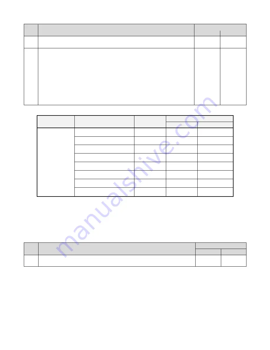
Table 8-2: Stowed resistance measurements (values apply only at NTP)
Lightband State
Object Being Measured
Pin
Connections
Resistance [
Ω]
Allowable (1)
Measured
Stowed
Motor A
2 , 4
8.0 to 11.0
Motor B
6 , 8
8.0 to 11.0
Deploy Limit Switch A
1 , 2
< 0.3
Deploy Limit Switch B
5 , 6
< 0.3
Stow Limit Switch A
3 , 4
> 1E7
Stow Limit Switch B
7 , 8
> 1E7
Stow Limit Switch A
4 , 9
< 0.3
Stow Limit Switch B
8 , 9
< 0.3
(1) Ensure the over limit (OL) indication on the resistance measurement device complies with the
maximum tolerance. This is the case for the DMM referenced in Table 2-5.
Step
Procedure
Date & Initials
Tech.
QA
8.4.13
If weights or a fixture were used to compress the Lightband, they may be
removed at this time. If LCTs were used, remove cable ties per section 17.5.


