1 Features and technical data
Installation, Use and Maintenance Manual – GAHP-A
7
▶
sealed combustion chamber (type C) suitable for outdoor
installations;
▶
metal mesh radiant burner equipped with ignition and flame
detection device, controlled by an electronic control unit;
▶
titanium stainless steel shell-and-tube water heat exchang-
er, externally insulated;
▶
stainless steel, flue gas latent heat recovery exchanger;
▶
air exchanger with finned coil, with steel pipe and alumini-
um fins;
▶
automatic microprocessor-controlled finned coil automatic
defrosting valve;
▶
standard or S1 silenced fan (reduction of electrical consump-
tion and reduction of sound emission).
Control and safety devices
▶
S61 electronic board with microprocessor, LCD display and
knob;
▶
Mod10 additional electronic board (integrated in S61);
▶
auxiliary W10 electronic board
▶
installation water flowmeter;
▶
generator limit thermostat, with manual reset;
▶
flue gas temperature thermostat, with manual reset;
▶
generator fin temperature sensor;
▶
sealed circuit safety relief valve;
▶
by-pass valve, between high and low pressure circuits;
▶
ionisation flame controller;
▶
gas solenoid valve with double shutter;
▶
anti-icing function for water circuit;
▶
condensate discharge obstruction sensor.
Standard or silenced fan
According to the type of fan the GAHP-A unit is available in two
versions:
▶
standard fan, for applications that do not require a special
degree of noiselessness;
▶
silenced fan, for applications that require a high degree of
noiselessness;
1�2 DIMENSIONS
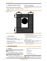
Figure 1�1 – Service plate
Hydraulic/gas unions detail
LEGEND
G
Gas fitting Ø ¾” F
B
Inlet water fitting Ø 1¼” F
A
Outlet water fitting Ø 1¼” F


