4 Electrical installer
28
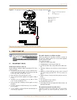
Figure 4�4 – Connexion câble CAN BUS for plants with one unit
LEGEND
DDC
direct digital control
SCH
electronic board S61
J1
Jumper CAN-BUS in board S61
J21
Jumper CAN-BUS in board DDC
A
terminal nodes connection - (3 wires; J1 e J21 = "closed")
H,L,GND
data signal wires (rif. cables table)
External request
(System (3) see also Paragraph 1.7 p. 16)
It is required to arrange:
▶
request device (e.g. thermostat, clock, button, ...) fitted with
a voltage-free NO contact.
How to connect the external request
Connection of external request is effected on the S61
board located in the Electrical Panel inside the unit (Fig-
ure 4.5 p. 28):
1. Access the Electrical Board of the appliance accord-
ing to the Procedure 4.2 p. 25.
2. connect the voltage free contact of the external de-
vice, through two conductor wires, to terminals R
and W (respectively: common 24 V AC and heating
enable) of electronic board S61 (Detail CS)
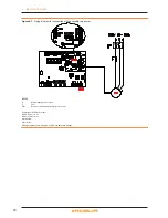
Figure 4�5 – Wiring diagram, external enable connection
Electrical connection to external operation enable
LEGEND
SCH
Electronic board
R
Common
W
Heating enable terminal
Components NOT SUPPLIED
CS
external enable


