


4 Electrical installer
24
1. Remove the front panel;
2. Fasten the collar (D) with its spacer to the left side
panel of the appliance;
3. Fit the terminal/pipe assembly (B) to the elbow (A).
4. Fit the rain cover (C) onto the elbow (A);
5. Remove the protection cover;
6. Insert the elbow/terminal/pipe assembly into the
flue gas exhaust;
7. Fit the assembly closing the collar (D) and place the
rain cover;
8. Fit the front panel back on.
The cap prevents water and foreign bodies entering
the appliance before the fumes kit is installed. The cap
should thus be removed only when the kit itself has
been fully assembled and installed.
Any flue
If necessary, the appliance may be connected to a flue.
▶
To size the flue refer to Table 1.1 p. 16 and Design Manual.
▶
If several appliances are connected to a single flue, it is ob-
ligatory to install a check valve on the exhaust of each.
▶
The flue must be designed, sized, tested and constructed by
a skilled form, with materials and components complying
with the regulations in force in the country of installation.
▶
Always provide a socket for flue gas analysis, in an accessible
position.
3�11 FLUE GAS CONDENSATE DISCHARGE
The GAHP-A unit is a condensing appliance and therefore pro-
duces condensation water from combustion flue gases.
Condensate acidity and exhaust regulations
The flue gas condensate contains aggressive acid sub-
stances. Refer to applicable regulations in force for con-
densate exhaust and disposal.
▶
If required, install an acidity neutraliser of adequate
capacity.
Do not use gutters to discharge the condensate
Do not discharge the fume condensate water in gutters,
due to the risk of materials corrosion and ice formation.
Flue gas condensate connection
The fitting for flue gas condensate discharge is located on the
left side of the appliance (Figure 3.3 p. 24).
▶
The distance L between the sleeve and the base must not
exceed 110 mm.
▶
The corrugated condensate discharge pipe must be con-
nected to a suitable discharge manifold.
▶
The junction between the pipe and the manifold must re-
main visible.
Flue gas condensate discharge manifold
To make the condensate discharge manifold:
▶
Size the ducts for maximum condensation capacity (Table
1.1 p. 16).
▶
Use plastic materials resistant to acidity pH 3-5.
▶
Provide for min. 1% slope, i.e. 1 cm for each m of the length
(otherwise a booster pump is required).
▶
Prevent freezing.
▶
Dilute, if possible, with domestic waste water (e.g. bath-
rooms, washing machines, dish washers...), basic and neu-
tralising.
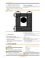
Figure 3�3 – Condensate drain position
A
B
D
L
LEGEND
A Condensate discharge hose
D Corrugated hose
3�12 DEFROSTING WATER DRAINAGE
Defrosting
In winter, frost may form on the finned coil and the ap-
pliance performs defrosting cycles.
Collection basin and drainage system
▶
Provide for a collection basin or containment rim and a dis-
charge system of the defrosting water, to avoid overflowing,
icing and damage.
4 ELECTRICAL INSTALLER
4�1 WARNINGS
General warnings
Read the warnings in Chapter III p. 4, providing im-
portant information on regulations and on safety.
Compliance with installation standards