


3 Heating engineer
Installation, Use and Maintenance Manual – GAHP-A
23
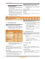
Gas pipes sizing
The gas pipes must not cause excessive load losses and, conse-
quently, insufficient gas pressure for the appliance.
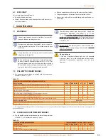
Supply gas pressure
The appliance's gas supply pressure, both static and dynamic,
must comply with Table 3.3 p. 23, with tolerance ± 15%.
Table 3�3 – Network gas pressure
Gas supply pressure
Product categories
Countries of destination
G20 [mbar]
G25 [mbar]
G30 [mbar]
G31 [mbar]
G25�1
[mbar]
G27 [mbar] G2,350 [mbar]
II
2H3B/P
AL, BG, CY, CZ, DK, EE, FI, GR,
HR, IT, LT, MK, NO, RO, SE,
SI, SK, TR
20
30
30
AT, CH
20
50
50
II
2H3P
AL, BG, CZ, ES, GB, HR, IE, IT,
LT, MK, PT, SI, SK, TR
20
37
RO
20
30
II
2ELL3B/P
DE
20
20
50
50
II
2Esi3P
FR
20
25
37
II
2HS3B/P
HU
25
30
30
25
II
2E3P
LU
20
50
II
2L3B/P
NL
25
50
50
II
2E3B/P
PL
20
37
37
II
2ELwLs3B/P
20
37
37
20
13
II
2ELwLs3P
20
37
20
13
I
2E(S); I3P
BE
20
25
37
I
3P
IS
30
I
2H
LV
20
I
3B/P
MT
30
30
I
3B
30
Non compliant gas pressure (Table 3.3 p. 23) may
damage the appliance and be hazardous.
Vertical pipes and condensate
▶
Vertical gas pipes must be fitted with siphon and discharge
of the condensate that may form inside the pipe.
▶
If necessary, insulate the piping.
LPG pressure reducers
With LPG the following must be installed:
▶
a first stage pressure reducer, close to the liquid gas tank;
▶
a second stage pressure reducer, close to the appliance.
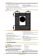
3�10 COMBUSTION PRODUCTS EXHAUST
Compliance with standards
The appliance is approved for connection to a combus-
tion products exhaust duct for the types shown in Table
1.1 p. 16.
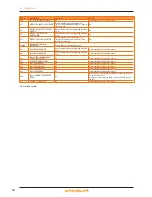
Flue gas exhaust connection
▶
Ø 80 mm (with gasket),
on the left, at the top (Figure 3.2 p. 23).
Flue gas exhaust kit
The appliance is supplied with flue gas exhaust kit, to be fitted
by the installer, including (Figure 3.2 p. 23):
▶
1 pipe Ø 80 mm, length 300 mm, with terminal and socket
for flue gas analysis;
▶
1 support collar;
▶
1 90° elbow Ø 80 mm;
▶
1 rain cover.
Figure 3�2 – Fume outlet
LEGEND
A
Curve 90° Ø 80
B
Pipe Ø 80 Lg.300 mm w/terminal
C
rain cover
D
Collar
How to install the flue gas kit
Figure 3.2 p. 23 J34: