The Settings of Failsafe
After the system work normally, press the PB1 for 5 seconds to save the position
data of every servo to the receiver R4047NB20.
The failsafe data takes effect only when SW2 is OFF. If the SW2 is ON, once out
of control,
the servo will keep the last position
. The failsafe settings are effective for
all of the 20 servos, but cannot be turned off or set individually.
Debugging
The receiving sensitivity depends on the background noise of the plane. So it is
very important to discover and adjust the position of the interference source.
Step one, no-load test for the receiver,
After binding the receiver, only take a battery for the range test. Do not carry cell
phones, cameras or any other electrical devices. The transmitter needs to enter the
DEBUG mode, otherwise there will be no result even if goes several kilometers away.
After the DEBUG mode is set, power up the transmitter and at this moment, the
transmitter will not produce warning tone of RF output. The transmitter can have no
antennas under the DEBUG mode.
Without the antenna, the remote range will be 5 meters, while with the antenna,
the distance will extend to tens of meters. With the distance increasing, the signal
strength indicators will reduce one by one. When the signal is poor, the RX LED
flashes irregularly, and the antenna selection indicator will switch frequently. If the
distance is close or the signal is strong but the RX blinks irregularly, it means that the
current frequency band is very dirty. Generally the 433ISM band will be very dirty in
most of cities, because all industrial devices use this frequency band. If the test fails,
you need to change to another frequency band .
Step two, after the receiver is installed, bind it after all airborne devices are
started. This binding aims to exclude the EMI interference from airborne devices.
Quality certified products generally have good electromagnetic compatibility, but the
others are likely to have electromagnetic leakage. The noise peak value in the UHF
frequency components may be apparent, and even the noise as weak as -100dBm may
reduce sensitivity of the receiver seriously.
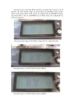
After the binding is completed, the receiver will display the highest value of EMI
in the current band.
LED1-LED5 all off indicates the input signal is less than -115dBm
LED1 is lit indicates the input signal is from -115 dBm to -109 dBm
LED2 is lit indicates the input signal is from -109 dBm to -103 dBm
LED3 is lit indicates the input signal is from -103 dBm to -97 dBm
LED4 is lit indicates the input signal is from -97dBm to -85 dBm
LED4 is lit indicates the input signal exceeds -85 dBm

