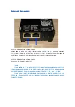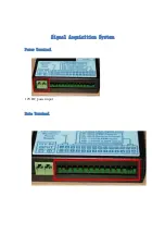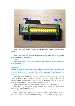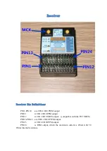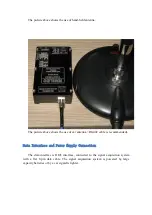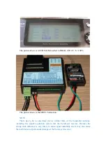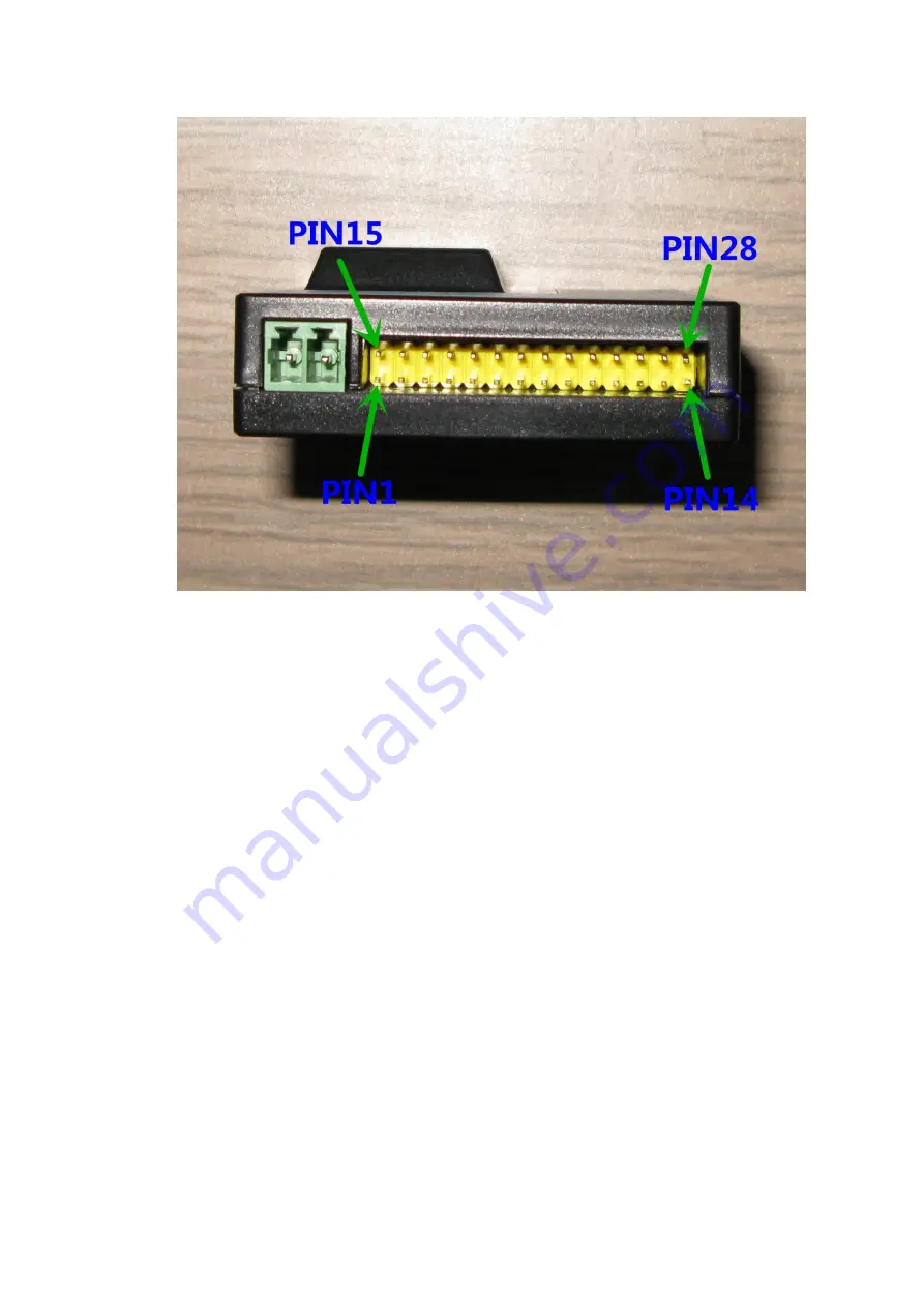
PIN1, PIN15 are ground. Connected to the negative terminal of the be-relayed
receiver.
PIN2, PIN16 are 4.8V positive power supply output, connected to the positive
power of the be-relayed receiver.
Note:
PIN1-PIN2 and PIN15-PIN16, which internally parallel, can provide two be-
relayed receiver .
Terminology:
Be-relayed receiver - This receiver:
does not
refer to R4047NB20, but means the
receiver which input data into the Signal Acquisition System, namely the original
receiver of the remote control equipment, the R6203SB and R6014HS, for
example.
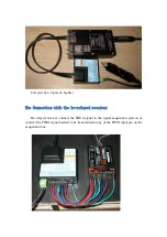
PIN3-PIN12 are PWM input, which are used to connect with the output terminal
of the R6014HS’s PWM output. The FUTABA servo, for example, white wire of
which is PWM signal. The PWM signal acquired by PIN3-PIN12 are corresponded to
the CH1-CH10 PWM output signal of R4047NB20 receiver.
PIN17-PIN26 are PWM input, which functions the same as PIN3-PIN12.
The PWM signal acquired by PIN17-PIN26 correspond to the CH11-CH20
PWM output of R4047NB20 receiver.
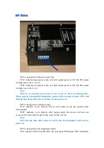
PIN13 is PPM input. If be-relayed equipment has PPM output interface, such as
head tracker or the receiver with PPM output, you can use PIN13 to input signal to


