26
FAMILY CONDENS KIS - FAMILY CONDENS IS
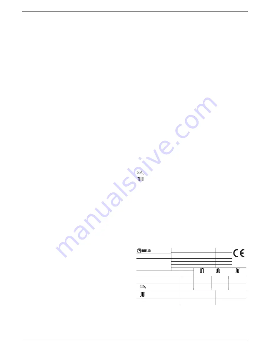
22 - SERIAL NUMBER PLATE
DHW operation
CH operation
Pmw
DHW maximum pressure
Pms
CH maximum pressure
Qn
nominal capacity
Pn
nominal power
Qm
Reduced heat delivery
Pm
Reduced heat output
IP
protection level
T
temperature
ŋ
working efficiency
D
specific capacity
NOx
NOx value class
18 - CHECKING COMBUSTION PARAMETER
Do as follows to analyze combustion:
- go to GAUGING & SERVICE and set the combustion analysis password
as given in paragraph “Adjustments”
- insert the analyzer probe into the specific openings on the air box, after
removing screw B and cap C (Fig. 46).
The fumes analysis probe must be introduced as far as possible
- screw the analyzer setscrews into the fumes analysis opening
- the first display gives the reading of the number of turns corresponding to
maximum heating power set on the boiler (see paragraph “Adjustments”
item P23)
A subsequent rotation of the encoder A turns on the boiler for the com-
bustion control
- check combustion
- refer to the “Adjustments” paragraph if the boiler has to be gauged
- remove the analyzer gauge and close the combustion analysis openings
by their screws.
IMPORTANT
The function switching off the boiler when the water temperature reaches
maximum limit of about 90°C will also stay on during combustion analysis.
19 - GAS CONVERSION
It is easy to transform gas from one family to gas belonging to another family
even with the boiler installed.
This job must be done by professionally qualified personnel only.
The boiler is supplied to run on natural gas (G20) – see the product rating
plate for details.
The boiler can be transformed to use propane gas using a special kit.
Follow the instructions given here below for disassembly:
- Switch off the power to the boiler and turn off the gas cock
- Remove the panel and casing
- Lift up and rotate the instrument panel
- Open the air box cover
For
2.5 KIS-IS
only: unscrew the screws fastening the silencer (A) and
remove it (Fig. 60)
- Disconnect the mixer gas ramp. Unscrew the clamp screws and relative
mixer springs to fan and then remove it.
- For
3.5 KIS-IS
only: unscrew the screws fixing the plastic Venturi to the
aluminium shell
- Loosen the plastic Venturi (B) - Fig. 44 - by levering from under the teeth
(BE CAREFUL NOT TO FORCE THEM) and press from the opposite side
until it is completely extracted from the aluminium shell.
- Using wrench CH6 remove and
DISGARD AND DO NOT RE-USE
the 2
nozzles (C), clean plastic debris from relative housing (Fig. 44)
- Press in the 2 new nozzles from the kit as far as the threaded part, then
screw in tightly
- Reassemble the mixer with the flap in a horizontal position and the spacer
springs placed at 120° as shown in the (Fig. 45)
- Reassemble gas ramp and silencer, working vice versa.
- Check the number of times the fan turns
- Switch on the power to the boiler and turn on gas cock again
- Fill in and stick on the accompanying transformation data label
- Close the air box cover
- Close up the instrument panel again
- Reassemble the casing and panel
Programme the “Gas type” parameter and regulate the boiler following the
instructions in the “Adjustments” section.
Transformation must be done by qualified personnel only.
After completing transformation, regulate the boiler again following
instructions given in the specific paragraph and apply the new identi
-
fication label from the kit.
General maintenance
Be particularly careful when handling the mixer: the Clapet juts out from the
body so that the mixer must be laid on the air inlet side (flap area) or make
sure the Clapet is inside the body if it has to be laid on the Clapet side.
The Clapet must never have to bear the weight of the mixer.
Clean the Venturi from any dust with an aspirator during the annual system
cleaning. Check that flap and Clapet are working correctly (all open at rated
flow, all closed at minimum flow)
Pmw = 6 bar T= 60
°
C
Qn =
NOx:
D:
Pms = 3 bar T= 90
°
C
Condensing Boiler
IP
Pn =
Qm =
Pm =
Pn =
50-30
°
C
80-60
°
C
80-60
°
C
RIELLO S.p.A.
Via Ing. Pilade Riello, 7
37045 Legnago (Vr)
N.
20 - MAINTENANCE
The appliance must be systematically controlled at regular intervals to
make sure it works correctly and efficiently and conforms to legislative pro
-
visions in force.
The frequency of controls depends on the conditions of installation and
usage, it being anyhow necessary to have a complete check carried out by
authorized personnel from the Servicing Centre every year.
- Check and compare the boiler’s performance with the relative specifica
-
tions. Any cause of visible deterioration must be immediately identified
and eliminated.
- Closely inspect the boiler for signs of damages or deterioration, particu
-
larly with the drainage and aspiration system and electrical apparatus.
- Check and adjust – where necessary – all the burner’s parameters.
- Check and adjust – where necessary – the system’s pressure.
- Analyze combustion. Compare results with the product’s specification.
Any loss in performance must be identified and corrected by finding and
eliminating the cause.
- Make sure the main heat exchanger is clean and free of any residuals or
obstruction.
- Check and clean – where necessary – the condensation tray to make
sure it works properly.
IMPORTANT
: always switch off the power to the appliance and close the
gas by the gas cock on the boiler before carrying out any maintenance and
cleaning jobs on the boiler.
Do not clean the appliance or any latter part with flammable substances
(e.g. petrol, alcohol, etc.).
Do not clean panelling, enamelled and plastic parts with paint solvents.
Panels must be cleaned with ordinary soap and water only.


