


SETTING THE MOTOR TYPE
MOTOR POSITIONING MANOEUVRE
PROGRAMMING THE TRAVEL DISTANCE AND PAUSE TIMES
I
GB
47
48
T624 is a versatile ECU that can be adapted to control most 24V automatic devices. The motor setting is only required for
certain models in order to optimise the parameters for that particular motor.
Procedure:
1 ) Keep the PROG. Button held down for (det. 15, fig. A) about 3 seconds until the led LD1 lights up (det. 18, fig. A)
2) Keep button P3 held down until the led LD1 flashes, release P3.
3) the led will now indicate which motor is being used by flashing every 2 seconds as follows:
a. 1 flash = STANDARD motor (default)
b. 2 flashes = MOLE motor
c. 3 flashes = ASY24REV motor
d. 4 flashes = ASYFAST motor
4) Press PP to change the selection, check the change in the number of flashes.
5) Once you have chosen the desired motor press Stop/Prog to memorise it.
The type of motor that has been set in the ECU will be indicated a soon as the programmer is powered up (or after it has been
reset) by the number of flashes indicated above.
warning:
- for a standard motor use the STANDARD setting (default value);
- using the motor parameters (which can be set via PRGLINK) you can optimise the performance of a vast range of motors.
Using this procedure we can set the type of motors that are connected to the ECU in order to prepare the installation for
programming and / or to determine whether or not the motors have been correctly installed.
During this procedure the buttons will work in the “manual mode” and all security devices will be ignored.
Procedure:
This programming procedure will detect and memorise all the work times that the motor requires in order to complete each
single opening and closing manouvre including the automatic reclosing times.
Two work time programming methods are available:
- 1) AUTOMATIC work time programming (simplified)
- 2) ADVANCED work time programming (manual)
The choice depends on the type of automation: the first choice (automatic) has fixed parameters such as gate delay
deceleration times, while the second choice (manual) allows you to precisely adjust the gate delay and deceleration area.
- If you are unsure which method to use, try the automatic mode first and only use the manual mode if the gates are
not operating as required.
- Manual programming is obligatory for asymmetrical systems where the gate that has to close first has a greater
angle of manoeuvre than the second gate leaf.
During the automatic detection procedure
During the work time programming stage P/P (part. 17 di fig.A) should be activated several times. In alternative you can use
P/P commands connected to binding post 14, fig. C) or a radio control transmitter that has already been memorised in channel
(P1).
The sequence will change according to the type of installation and the travel limit will be automatically detected by the
ENCODER sensor (optional connection) as an alternative to the current sensor integrated in the ECU.
If the encoder has been installed the ECU will memorise the effective gate movement SPACE. If encoder sensors are
not detected during programming, the ECU will compensate by detecting and memorising each gate work cycle
individually.
Important notes to read before programming:
A. Make sure the movement area of the gate is free of obstacles and that you are not interfering with any photoelectric cells or
sensors connected to the ECU.
B. Make sure the opening and closing direction mechanical travel limits have been installed on both gate leaves and
that they
are robust enough to be able to a moving gate.
C. Set the trimmer (part 21, fig. A) to about half way for the first programming cycle. If the motor is not able to complete the
manoeuvre increase the torque by rotating the trimmer clockwise.
D. If you are only using one motor, set dip 11 to OFF and wire it to M1.
E. If the installation has two gates (sliding or hinged) set dip 11 to ON. The motor wired to M1 will move first in the opening
direction and its gate will have the electric lock fitted to it. Motor M2 will start to close first during normal operation (the self-
learning cycle has a difference sequence of movement).
Execute one of the following procedures:
AUTOMATIC PROGRAMMING (simplified)
DIP 9 ON DURING programming
for a self-learning cycle that decelerates after 5 seconds so it can find the mechanical travel
limit safely. Use this setting for long and/or heavy.
DIP 9 OFF DURING programming
for rapid mechanical travel limit detection (without deceleration).
DIP 9 set to ON only AFTER programming
. The set deceleration times will be enabled
Before beginning programming check the correct settings and connections by observing the leds (det. 22, fig. A):
Led
BSC, BSA, FT1, FT2, J2 and STP
must be LIT.
Led
J1, PC, PA, PED and P/P
must be OFF.
1
3
2
4
5
6
STOP
Reset
M1
M1
M1
M1
M2
M2
M2
M2
P3
P/P
LD1
PROG.
Hold down button P3 (part. 16, fig. A) and reset the ECU by short circuiting the binding posts
(det. 14, fig.1).
After about 3 seconds led LD1 will light up (det. 18, fig. A) as well as the warning light, release
button P3.
The procedure has been activated.
Press the PROG button to
OPEN M2
(if the motor closes invert
wires 30 and 31).
Press the button P/P to
OPEN M1
(if the motor closes invert wires
35 and 36).
Press P3 and PROG, motor
M2 will CLOSE
.
Press P3 and P/P, motor
M1 will CLOSE
.
To get back to the normal operating mode, reset the ECU (by short
circuiting the binding posts, det. 14, fig.A).
PROG.
PROG.
P3
P3
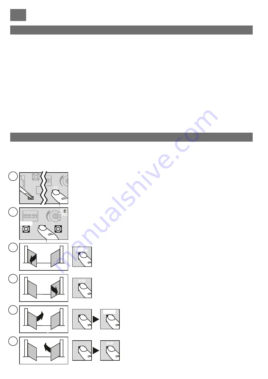
Cut off the power to the ECU and disconnect any eventual batteries during programming.
Release the gate leaves and move them to an almost fully open position.
Rearm the motor gears and power up the installation.
Hold down the PROG button (part. 15, fig. A) for about 3 seconds until led LD1 lights up
(part. 18, fig. A)
The ECU is now in the programming stage.
Press the P/P button (part. 17, fig. A) the gate with motor M2 should begin to close,
if it moves in the opening direction instead, stop programming by switching off the
power, invert the wires (21 - 22) of motor M2 and repeat the procedure from point
(1).
2
STOP
M1
M2
P3
P/P
LD1
PROG.
2
3
GB
Summary of Contents for Cardin T624
Page 3: ...222 190 150 50 118 280 220 Fig B mm 2 ...
Page 80: ...ZVL609 00 ...


