


2916050
8
GB
Technical description of the burner
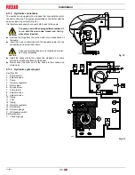
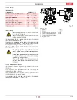
3.4
Packaging - weight (Approximate measurements)
The burners is supplied skid mounted. Outer dimensions of
packaging are indicated in Fig. 1.
The weight of the burner complete with packaging is indicated
in Tab. F.
Tab. F
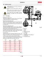
3.5
Overall dimensions
The maximum dimensions of the burner are given in Fig. 2.
Keep in mind that inspection of the combustion head requires the
burner to be opened and the rear part withdrawn on the slide bars.
The maximum dimension of the burner when open, without casing,
is given in measurement I.
Tab. G
(1)
Blast tube: short - long (obtainable with kit).
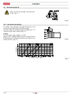
3.6
Standard equipment
The burner is supplied complete with:
Screws to secure the burner flange to the boiler 1/2 W . . . . . No. 4
Flexible hoses . . . . . . . . . . . . . . . . . . . . . . . . . . . . . . . . . . . . No. 2
Gaskets for flexible hoses . . . . . . . . . . . . . . . . . . . . . . . . . . . No. 2
Adaptor G 1/8” / 1/8” NPT . . . . . . . . . . . . . . . . . . . . . . . . . . . No. 1
Burner head gasket . . . . . . . . . . . . . . . . . . . . . . . . . . . . . . . . No. 1
Instruction booklet and spare parts list. . . . . . . . . . . . . . . . . . No. 1
inch
A
B
C
lbs
RL 70/M
45 9/32”
23 5/8”
31 3/16”
143
RL 100/M
45 9/32”
23 5/8”
31 3/16”
150
RL 130/M
45 9/32”
23 5/8”
31 3/16”
157
D36
Fig. 1
Fig. 2
D1217
inch
A
B
C
D
E
F
(1)
G
H
I
(1)
RL 70/M
26 1/8”
11 21/32” 14 15/32”
21 27/32” 26 25/32”
10 23/32”-15 5/32”
7 1/16”
16 15/16”
37 7/16”-42 3/4”
RL 100/M
26 1/8”
12 9/32”
14 15/32”
21 27/32” 26 25/32”
10 23/32”-15 5/32”
7 1/16”
16 15/16”
37 7/16”-42 3/4”
RL 130/M
27 3/4”
13 5/16”
14 15/32”
21 27/32”
26 25/32”
10 23/32”-15 5/32”
7 7/16”
16 15/16”
37 7/16”-42 3/4”


