


Installation
15
2916050
GB
4.6
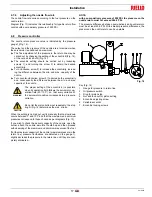
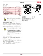
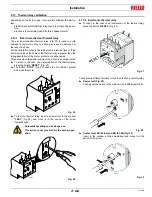
Securing the burner to the boiler
Disassemble the blast tube 9)(Fig. 8) from the burner 6) by pro-
ceeding as follows:
loosen the four screws 3) and remove the cover 1);
remove the screws 2) from the two slide bars 5);
remove the two screws 4) fixing the burner 6) to the flange 7);
withdraw the blast tube 9) complete with flange 7) and slide
bars 5).
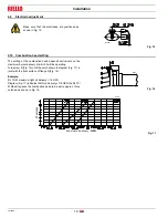
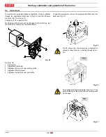
4.6.1
Combustion head calibration (RL 130/M)
At this point check, whether the maximum delivery of the burner is
contained in area B) or in area C) of the firing rate. See Fig. 4 on
page 10.
If it is in area B) then no operation is required.
If, on the other hand, it is in area C):
unscrew the screws 1)(Fig. 9) and disassemble the blast
tube 5);
unscrew the screws 3) and remove the shutter 4);
tighten the screws 3) on the rod 2);
now refit the blast tube 5) and the screws 1).
Once this operation has been carried out (if required):
secure flange 7)(Fig. 8) to the boiler plate inserting the sup-
plied gasket 8).
Use the 4 screws provided after having protected the thread
with an anti-seize product.
WARNING
The burner-boiler seal must be airtight.
Fig. 8
D1219
Fig. 9
D690