


2916050
20
GB
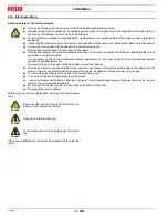
Installation
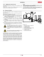
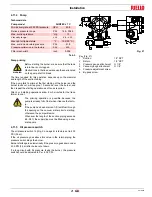
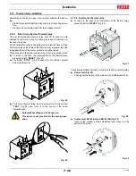
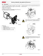
4.11.2 Hydraulic connections
The pumps are equipped with a by-pass that connects the return
line and suction line. The pumps are installed on the burner with the
by-pass closed by screw 6)(Fig. 20).
It is therefore necessary to connect both hoses to the pump.
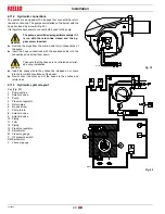
Remove the plugs from the suction and return connections of
the pump.
Insert the hose connections with the supplied seals into the
connections and screw them down.
Install the hoses where they cannot be stepped on or come
into contact with hot surfaces of the boiler.
Now connect the other end of the hoses to the suction and
return lines.
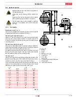
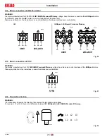
4.11.3 Hydraulic system layout
Pump suction
2
Solenoid valve
3
Pump
4
Pressure regulator
5
Return pipe
6
By-pas screw
7
Pump return
8
Solenoid valve
9
Solenoid valve
10 Piping
11 Filter
12 Piping
13 Pressure regulator
14 Servomotor
M Pressure gauge
P
Oil pressure switch
SM Servomotor
V
Vacuum gauge
WARNING
The pump seal will be damaged immediately if it
is run with the return line closed and the by-
pass screw inserted.
CAUTION
Take care that the hoses are not stretched or twist-
ed during installation.
D1224
Fig. 19
D2444
Fig. 20


