


Installation
17
2916050
GB
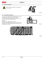
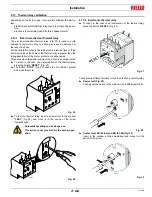
4.7.4
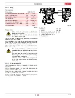
Adjusting the nozzle flow rate
The nozzle flow rate varies according to the fuel pressure on the
nozzle return.
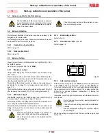
Diagram (Fig. 13) indicates this relationship for type A4 return flow
nozzles with pump delivery pressure of 290 PSI.
NOTE:
with a pump delivery pressure of 290 PSI, the pressure on the
nozzle return must not exceed 246.5 PSI.
The pressure difference between pump delivery and nozzle return
must be at least 43.5 PSI. With smaller pressure differences, the
pressure on the nozzle return can be unstable.
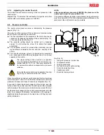
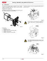
4.8
Pressure controller
The nozzle return pressure value is indicated by the pressure
gauge 1)(Fig. 14).
The output and the pressure of the nozzle are at maximum when
the servomotor is positioned on maximum.
The fine adjustment of the pressure in the return line may be
carried out by changing the setting of the eccentric 6)(Fig. 14),
of the nut and lock-nut 4)(Fig. 14).
The eccentric setting should be carried out by loosening
screws 7), and turning the screw 5) to obtain the desired
eccentricity.
Turn clockwise, screw 5) to increase the eccentricity, increas-
ing the difference between the min. and max. capacity of the
nozzle.
Turn counter-clockwise, screw 5) to decrease the eccentricity
and, consequently the difference between the min. and max.
capacity of the nozzle.
When the setting is carried out, verify manually that no slow-down
occurs between 0° and 130° and that the maximum and minimum
pressures correspond to those chosen as per diagrams (Fig. 13).
If you wish to check the delivery capacity of the nozzle, open the
burner, attach the nozzle, simulate the start-up and then proceed
with observing of the maximum and minimum pressures of the fuel.
If at the maximum capacity of the nozzle (maximum pressure in the
return line) pressure fluctuations are detected on the gauge 1),
slightly decrease the pressure in the return line until they are com-
pletely eliminated.
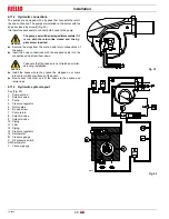
Gauge for pressure in return line
2
Oil pressure switch
3
Ring for piston stop
4
Nut and lock-nut for piston setting
5
Eccentric adjusting screw
6
Variable eccentric
7
Eccentric locking screws
WARNING
The proper setting of the eccentric 6) is possible
when its operation field follows the servomotor op-
eration field (20°-130°): so, that every variation of
the servomotor position corresponds to a pressure
variation.
CAUTION
Do not let the piston bottom out repeatedly: the stop
ring 3)(Fig. 14) determines the max. stroke.
D1227
Fig. 14


