background image

‐ 

14

 ‐ 


INSTALLAZIONE 


P

REDISPOSIZIONE ALL

INSTALLAZIONE


TUTTE LE OPERAZIONI DESCRITTE IN QUESTA SEZIONE DEVONO ESSERE ESEGUITE 
ESCLUSIVAMENTE DA PERSONALE QUALIFICATO. 

L’Azienda non si assume nessuna responsabilità per danneggiamenti causati da collegamenti errati o da 
operazioni non descritte in questo manuale.


PRIMA DELL’INSTALLAZIONE FARE RIFERIMENTO AL MANUALE “INSTALLATION INSTRUCTIONS” 
FORNITO IN DOTAZIONE. 


Tale manuale, fornito anch’esso con l’UPS, contiene dati molto importanti per l’installazione come ad esempio: 


Le viste quotate dell’UPS; 

  La vista dell’appoggio sul pavimento per il dimensionamento di un eventuale struttura per rialzare 

l’armadio; 


La posizione dell’entrata cavi; 


La posizione  dei ventilatori dell’UPS; 


Informazioni per il dimensionamento dei cavi di ingresso, uscita e di  batteria; 


Dettagli relativi alla connessione come ad esempio le viste quotate delle morsettiere 


Informazioni relative all’installazione come ad esempio la potenza dissipata dall’apparecchiatura (kW).


L’UPS È MUNITO DI RUOTE PER LA MOVIMENTAZIONE; PREDISPORRE UNA LUNGHEZZA DEI CAVI DI 
CONNESSIONE SUFFICIENTE A POTER SPOSTARE L’UPS PER EVENTUALI OPERAZIONI DI 
MANUTENZIONE 


A

MBIENTE D

INSTALLAZIONE


Per la scelta del luogo d'installazione dell’UPS e dell'eventuale Battery Box osservare le seguenti note: 


L’UPS e/o Battery Box devono essere installati a debita distanza da pareti o altri ostacoli. Per maggiori informazioni 
fare riferimento al manuale 

“Installation Instructions”

 fornito in dotazione 


evitare gli ambienti polverosi 


verificare che il pavimento sia in piano e in grado di sostenere il peso dell’UPS (e del Battery Box) 


evitare ambienti troppo angusti che potrebbero impedire le normali operazioni di manutenzione 


l'umidità relativa ambiente non deve superare il 90%, senza condensa 


verificare che la temperatura ambiente, con UPS funzionante, si mantenga tra 0 e 40°C 


L’UPS è in grado di funzionare con una temperatura ambiente compresa tra 0 e 40°C. La temperatura 
consigliata di funzionamento dell’UPS e delle batterie è compresa tra 20 e 25°C. Se infatti la vita operativa 
delle batterie è mediamente di 5 anni con una temperatura di funzionamento di 20°C, portando la 
temperatura operativa a 30°C la vita si dimezza. 


evitare il posizionamento in luoghi esposti alla luce diretta del sole o ad aria calda 

 
Per mantenere la temperatura del locale di installazione nel campo sopra indicato occorre prevedere un sistema di smaltimento 
del calore dissipato (il valore delle kW / kcal/h / B.T.U./h dissipate dall’UPS è indicato nella tabella riportata nel manuale 

“Installation Instructions”

 in dotazione).  

 
I metodi utilizzabili sono i seguenti: 


ventilazione naturale 


ventilazione forzata

, consigliata se la temperatura esterna è inferiore (es. 20°C) alla temperatura alla quale si vuole 

fare funzionare l’UPS e/o il Battery Box (es. 25°C) 


impianto di condizionamento

, consigliato se la temperatura esterna è superiore (es. 30°C) alla temperatura imposta per 

il funzionamento dell’UPS e/o del Battery Box (es. 25°C) 


Summary of Contents for Multi Sentry 160 MST

Page 1: ......

Page 2: ......

Page 3: ... ambientale sviluppato dall azienda in accordo con la normativa vigente In questo prodotto non sono presenti materiali pericolosi come CFC HCFC o amianto L imballo è costituito da MATERIALE RICICLABILE Smaltire i singoli elementi secondo la normativa vigente nel paese di utilizzo del prodotto Fare riferimento alla seguente tabella per l identificazione dei materiali DESCRIZIONE MATERIALE Pallet Le...

Page 4: ...RICAMBIO ARIA PER LOCALE BATTERIA 15 RIMOZIONE DELL UPS DAL PALLET 16 CONTROLLO DEL CONTENUTO DELLA SCATOLA ACCESSORI 18 POSIZIONAMENTO DELL UPS 18 COLLEGAMENTI ELETTRICI 19 DIMENSIONAMENTO DEI CAVI DI COLLEGAMENTO 19 OPERAZIONI PRELIMINARI ALLE CONNESSIONI 19 CONNESSIONI DELL UPS 20 SCHEMI DI CONNESSIONE ALL IMPIANTO ELETTRICO 21 PROTEZIONI 24 PROTEZIONE DA CORTOCIRCUITO 24 PROTEZIONI DA RITORNI ...

Page 5: ...VENTOLE 33 DISPLAY GRAFICO 34 MENU DISPLAY 36 MODALITÀ DI FUNZIONAMENTO 37 BYPASS MANUALE SWMB 37 ALIMENTATORE AUSILIARIO RIDONDANTE PER BYPASS AUTOMATICO 38 POWER WALK IN 38 DECLASSAMENTO DELLA POTENZA PER CARICHI 220 200 208V FASE NEUTRO 38 CONFIGURAZIONE UPS 39 PORTE DI COMUNICAZIONE 41 CONNETTORI RS232 E USB 41 COMMUNICATION SLOT 41 PORTA AS400 42 SEGNALATORE ACUSTICO BUZZER 43 SOFTWARE 44 SOF...

Page 6: ...sima generazione hanno permesso di raggiungere elevate prestazioni quali ZERO IMPACT SOURCE garantisce bassa distorsione d ingresso fattore di potenza prossimo a uno e massima compatibilità con il gruppo elettrogeno BATTERY CARE SYSTEM permette la gestione personalizzata delle batterie per le diverse topologie e il monitoraggio continuo delle stesse aumentandone così l efficienza e la durata SMART...

Page 7: ... 7 VISTE ANTERIORI UPS Pannello di controllo con display grafico Piedi di stazionamento dell UPS Griglie di aerazione Ruote per la movimentazione dell UPS Porta frontale con serratura ...

Page 8: ...faccia utente Da sinistra a destra Sezionatore di ingresso SWIN Sezionatore di ingresso bypass SWBYP Sezionatore di bypass manuale SWMB Sezionatore di uscita SWOUT Ventole moduli potenza Ventole bypass primarie ...

Page 9: ...nistra a destra Connettore Remote Emergency Power Off R E P O Porta contatti AS400 Porta comunicazione USB Porta comunicazione RS232 Pulsante partenza da batteria COLD START Slot per schede accessorie di comunicazione Alloggiamento Scheda Parallelo UPS opzionale ...

Page 10: ... 10 VISTA POSTERIORE UPS Ventole controllo Accesso collegamenti IN OUT Accesso contatti ausiliari Ventole bypass secondarie Ventole caricabatterie ...

Page 11: ...rsettiera dell UPS BATTERY N Connessioni di potenza E NEUTRO DI BATTERIA INPUT L1 L2 L3 N Connessioni di potenza FASI E NEUTRO DI INGRESSO BYPASS L1B L2B L3B Connessioni di potenza FASI BYPASS SEPARATO OUTPUT L1 L2 L3 N Connessioni di potenza FASI E NEUTRO DI USCITA PE Connessioni di potenza TERRA ...

Page 12: ...er ausiliario sezionatore d uscita remoto AUX RELAY SLOT Slot Relè INGRESSO BYPASS SEPARATO QUESTA SERIE DI UPS PUÒ ESSERE CONFIGURATA IN MODALITÀ DUAL INPUT OSSIA CON LINEA DI BYPASS SEPARATA DA QUELLA DI INGRESSO In questo caso viene consentito un collegamento distinto tra la linea d ingresso e la linea di bypass L uscita dell UPS sarà sincronizzata alla linea di bypass in modo che in caso di in...

Page 13: ...zionamento da batteria con preallarme di fine scarica o shutdown imminente Lampeggiante in Stand by funzione di riaccensione programmata attiva e rete assente LED carico su bypass Acceso fisso carico alimentato da linea bypass LED stand by allarme Acceso fisso allarme presente Lampeggiante stato di Stand by LED batterie da sostituire Acceso fisso batterie da sostituire Lampeggiante allarme sovrate...

Page 14: ...ggiori informazioni fare riferimento al manuale Installation Instructions fornito in dotazione evitare gli ambienti polverosi verificare che il pavimento sia in piano e in grado di sostenere il peso dell UPS e del Battery Box evitare ambienti troppo angusti che potrebbero impedire le normali operazioni di manutenzione l umidità relativa ambiente non deve superare il 90 senza condensa verificare ch...

Page 15: ...concentrazione di idrogeno emesso durante la carica dalle batterie al di sotto del limite di pericolo L aria di ricambio del locale deve essere assicurata preferibilmente per ventilazione naturale nel caso in cui questo non fosse possibile mediante ventilazione forzata La norma EN 50272 2 per il ricambio d aria prevede che l apertura minima deve soddisfare la seguente relazione A 28 x Q 28 x 0 05 ...

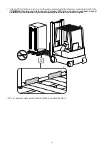
Page 16: ... di chiusura posti ai lati dell imballo Aprirli sollevandoli come mostrato in figura Sollevare il coperchio ed aprire la scatola di cartone Rimuovere il contenitore accessori NOTA la scatola accessori potrebbe trovarsi all interno dell imballo o dietro la porta dell UPS Rimuovere le 2 staffe che fissano l UPS al pallet 2 viti fissate all UPS 5 viti fissate al pallet ...

Page 17: ...ento delle forche ATTENZIONE Ogni qual volta ci sia la necessità di sollevare l UPS prima di procedere si raccomanda sempre di posizionare le forche solamente nei punti indicati dalle apposite etichette come mostrato in figura NOTA si consiglia di conservare tutte le parti dell imballo per eventuali utilizzi futuri ...

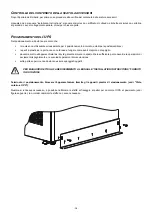
Page 18: ...ca e la porta non sono idonee a fungere come punti di spinta o di appiglio davanti e dietro all apparecchiatura si dovrà garantire almeno lo spazio libero sufficiente per consentire le operazioni di avviamento spegnimento e le eventuali operazioni di manutenzione sulla parte superiore non dovranno essere appoggiati oggetti PER MAGGIORI DETTAGLI FARE RIFERIMENTO AL MANUALE INSTALLATION INSTRUCTIONS...

Page 19: ...fettuare è quella del conduttore di protezione cavo di terra da collegare alla vite siglata PE L UPS deve funzionare con il collegamento all impianto di terra Il Neutro d ingresso deve essere sempre collegato ATTENZIONE è richiesto un sistema di distribuzione trifase a 4 fili La versione standard dell UPS deve essere collegata ad una linea di alimentazione 3 Fasi Neutro PE terra di protezione di t...

Page 20: ... UPS collegare il conduttore di protezione cavo di terra alla barra per le connessioni di potenza a terra siglata PE collegare i cavi d ingresso di bypass d uscita e di batteria alla morsettiera rispettando le posizioni e le polarità indicate nella sezione Vista connesssioni UPS Collegare i cavi N BATT N INPUT N BYPASS e N OUTPUT alla barra di neutro Rimuovere i ponticelli presenti tra le barre d ...

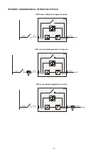
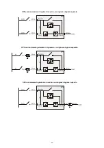
Page 21: ... 21 SCHEMI DI CONNESSIONE ALL IMPIANTO ELETTRICO UPS senza variazione di regime di neutro UPS con isolamento galvanico in ingresso UPS con isolamento galvanico in uscita ...

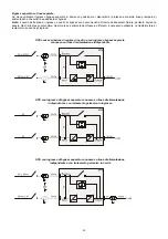
Page 22: ...senza variazione di regime di neutro e con ingresso bypass separato UPS con isolamento galvanico in ingresso e con ingresso bypass separato UPS con isolamento galvanico in uscita e con ingresso bypass separato ...

Page 23: ...ovranno essere riferiti allo stesso potenziale Qualora le due alimentazioni fossero differenti è necessario utilizzare un trasformatore di isolamento su uno degli ingressi UPS senza variazione di regime di neutro e con ingresso bypass separato connesso su linea di alimentazione indipendente UPS con ingresso di bypass separato connesso su linea di alimentazione indipendente e con isolamento galvani...

Page 24: ...arico su bypass Se il guasto si verifica con UPS in funzionamento da batteria il carico rimane non alimentato Volendo evitare lo spegnimento dell inverter e mantenere quindi il carico alimentato da inverter anche in caso di doppio guasto mancanza di rete e guasto interno è possibile personalizzare il sistema in modo da comandare la bobina di apertura di un interruttore posto a monte riprogrammando...

Page 25: ...fferenziale a monte del punto in cui la linea si divide per alimentare gli ingressi raddrizzatore e by pass del UPS protetti da interruttore magnetotermico Vedi figura seguente Versioni PARALLELO Per evitare falsi interventi in presenza di più macchine in parallelo deve essere inserito un unico interruttore differenziale a monte dell intero sistema Vedi figura seguente In funzionamento con tension...

Page 26: ...UPS vedi Sezione contatti ausiliari sono disponibili i morsetti per collegare i contatti ausiliari dei sezionatori bypass di manutenzione remoto e uscita remoto Questi sono identificati rispettivamente dalle diciture SERVICE BYPASS e AUX SWOUT Per l installazione fare riferimento ai paragrafi Sezione contatti ausiliari e Bypass di manutenzione remoto SERVICE BYPASS Prima di effettuare il collegame...

Page 27: ...ito dal costruttore eventuali utilizzi non conformi a quanto specificato possono causare malfunzionamenti o rotture all apparecchiatura Per l eventuale installazione collegare il cavo contenuto nell apposito kit al connettore EXT BATT TEMP vedi Sezione contatti ausiliari seguendo le indicazioni riportate nel relativo manuale Dopo l installazione effettuare l abilitazione della funzione di misurazi...

Page 28: ... UPS Utilizzare cavo doppio isolamento di sezione 1mmq per il collegamento dei morsetti SERVICE BYPASS e AUX SWOUT ai relativi contatti ausiliari dei sezionatori BYPASS DI MANUTENZIONE REMOTO 3 e USCITA 2 Verificare la compatibilità fra il Bypass di manutenzione remoto ed il regime di neutro d impianto SCHEMA DI INSTALLAZIONE DEL BYPASS DI MANUTENZIONE REMOTO Quadro elettrico periferico Connession...

Page 29: ...e UPS Nel caso di UPS connessi in parallelo non sono disponibili le modalità di funzionamento ECO LINE INTERACTIVE SMART SMART ACTIVE e STBYOFF STAND BY OFF Per il collegamento in parallelo degli UPS è necessario il kit parallelo opzionale Per maggiori informazioni riferirsi al manuale del kit parallelo TOP CABLE ENTRY Accessorio opzionale costituito da un particolare armadio da affiancare all UPS...

Page 30: ...ppresentato lo schema a blocchi dell UPS e vengono descritte le singole parti che lo compongono Diagramma a blocchi dell UPS IMPORTANTE I nostri gruppi di continuità sono concepiti e realizzati per una lunga durata anche nelle condizioni di servizio più severe Si ricorda tuttavia che si tratta di apparecchiature elettriche di potenza e come tali necessitano di controlli periodici Inoltre alcuni co...

Page 31: ...tteria esterna all UPS Dopo aver verificato la corretta polarità delle connessioni chiudere il sezionatore fusibili della linea di batteria esterna all UPS ATTENZIONE se è stato effettuato un collegamento non conforme a quanto riportato nel manuale Installation Instructions potrebbero essersi danneggiati i fusibili di batteria e altre protezioni in questo caso chiamare l assistenza per evitare ult...

Page 32: ...ONE è necessario configurare l UPS per settare i valori corretti della capacità nominale complessiva di batteria Tale operazione deve essere effettuata tramite il software di configurazione dedicato e riservato al personale del Serivice Dal menu principale premere il tasto per entrare nel menu di accensione Alla richiesta di conferma selezionare SI premere per confermare ed attendere qualche secon...

Page 33: ...nuovamente il pulsante per confermare Si accendono tutti i led attorno al display per 1 sec circa ed il buzzer inizia ad emettere un beep ogni 7 sec La sequenza di accensione termina quando l UPS si predispone nello stato funzionamento da batteria Nota se non viene eseguita la sequenza appena descritta entro 1 min l UPS si spegne autonomamente per non scaricare inutilmente le batterie SPEGNIMENTO ...

Page 34: ...r Battery Line Inverter Load Inverter Output Line Battery Charge Automatic Static Bypass Lo schema mostra lo stato dei tre moduli logici di potenza PFC Converter Inverter Automatic Static Bypass Ogni modulo può assumere uno dei seguenti stati Modulo Spento Modulo acceso in funzionamento normale Modulo in allarme o in blocco I seguenti simboli invece rappresentano il flusso di energia da e verso le...

Page 35: ... Zona di visualizzazione dello stato di funzionamento dell UPS La prima riga è sempre attiva e visualizza costantemente lo stato dell UPS in quell istante La seconda si attiva solo in presenza di un eventuale errore e o guasto dell UPS e mostra il tipo di errore guasto riscontrato A destra ogni rispettiva riga visualizza il codice corrispondente all evento in corso FUNZIONE TASTI Zona divisa in qu...

Page 36: ... 36 MENU DISPLAY ...

Page 37: ...quenza nominale ed il bypass non è più utilizzabile free running mode ATTENZIONE Nel caso di UPS connessi in parallelo non sono disponibili le modalità di funzionamento ECO LINE INTERACTIVE SMART SMART ACTIVE e STBYOFF STAND BY OFF BYPASS MANUALE SWMB ATTENZIONE in caso si notino malfunzionamenti contattare il centro assistenza La manutenzione dell UPS può essere eseguita unicamente da personale q...

Page 38: ...LK IN L UPS è dotato di serie della modalità Power Walk In attivabile e configurabile tramite il software di configurazione Quando la modalità è attiva al ritorno rete dopo un periodo in autonomia l UPS ritorna ad assorbire dalla stessa in modo progressivo per non mettere in crisi a causa dello spunto un eventuale gruppo elettrogeno installato a monte La durata del transitorio è impostabile da 1 a...

Page 39: ...t 2 sec viene reimpostata automaticamente la lingua inglese La modifica della funzione può essere bloccata tramite il software di configurazione Nella seguente tabella sono elencate le configurazioni che possono essere modificate tramite il software di configurazione in dotazione ai centri assistenza FUNZIONE DESCRIZIONE PREDEFINITO Operating mode Modalità di funzionamento dell UPS ON LINE Output ...

Page 40: ...onamento in modalità ECO Normal Eco mode min max threshold Range di tensione ammesso per il funzionamento in modalità ECO Low 200V High 253V UPS without battery Modalità di funzionamento senza batterie per convertitori di frequenza stabilizzatori Operating with Batteries Battery low time Tempo rimanente di autonomia stimata per il preavviso di fine scarica 3 min Automatic battery test Intervallo d...

Page 41: ...ONNETTORE RS232 CONNETTORE USB PIN NOME TIPO SEGNALE PIN SEGNALE 1 IN 1 VBUS 2 TX OUT TX linea seriale 2 D 3 RX IN RX linea seriale 3 D 4 4 GND 5 GND POWER 6 OUT 7 8 15V POWER Alimentazione isolata 15V 5 80mA max 9 WKATX OUT Risveglia alimentatore ATX COMMUNICATION SLOT L UPS è fornito di due slot di espansione per schede di comunicazione accessorie che consentono all apparecchiatura di dialogare ...

Page 42: ...de a funzionare da inverter Se il ponticello viene rimosso in mancanza di rete l UPS riprende il funzionamento da batteria 4 5 12 BATTERY LOW OUTPUT 1 Segnala che le batterie sono a fine scarica quando il contatto 5 12 è chiuso 1 6 13 14 BATTERY WORKING OUTPUT 2 Segnala che l UPS sta funzionando da batteria quando il contatto 6 14 è chiuso 1 9 10 LOCK OUTPUT 3 Quando il contatto è chiuso segnala c...

Page 43: ...nserimento di un carico distorcente Suono C La segnalazione viene fatta quando l UPS passa in funzionamento da batteria prima della segnalazione di fine scarica suono D È possibile tacitare la segnalazione vedi paragrafo Display grafico Suono D La segnalazione viene effettuata in funzionamento da batteria quando si raggiunge la soglia di allarme di fine scarica È possibile tacitare la segnalazione...

Page 44: ...ma operativo desiderato Collegare la porta di comunicazione RS232 dell UPS ad una porta di comunicazione COM del PC tramite il cavo seriale in dotazione oppure collegare la porta USB dell UPS ad una porta USB del PC utilizzando un cavo standard USB Seguire le istruzioni del programma di installazione Per informazioni più dettagliate sull installazione e l utilizzo consultare il manuale del softwar...

Page 45: ...RO LA PORTA SWIN È APERTO Chiudere il sezionatore MANCANZA DELLA TENSIONE DI RETE BLACKOUT Verificare la presenza della tensione di rete elettrica Eventualmente eseguire l accensione da batteria per alimentare il carico INTERVENTO DELLA PROTEZIONE A MONTE Ripristinare la protezione Attenzione verificare che non sia presente un sovraccarico o corto in uscita all UPS NON ARRIVA TENSIONE AL CARICO MA...

Page 46: ...IONAMENTO NELLO STADIO DI INGRESSO DELL UPS Azionare il bypass manuale SWMB spegnere e poi riaccendere l UPS Escludere il bypass manuale Se il problema permane contattare il centro assistenza più vicino LA FASE 1 PRESENTA UNA TENSIONE MOLTO MINORE DELLE ALTRE DUE FASI SBILANCIAMENTO DELLE TENSIONI Aprire SWIN effettuare l accensione da batteria attendere la fine della sequenza e chiudere SWIN IL D...

Page 47: ... accensione andando nel menù ACCENSIONE IL DISPLAY VISUALIZZA UNO O PIÙ DEI SEGUENTI CODICI F06 F07 F08 SEZIONAMENTO D INGRESSO IN CORTOCIRCUITO Azionare il bypass manuale SWMB spegnere l UPS aprire SWIN e contattare il centro di assistenza più vicino Attenzione una volta aperto SWIN non è più possibile richiuderlo prima dell intervento dell assistenza IL DISPLAY VISUALIZZA UNO O PIÙ DEI SEGUENTI ...

Page 48: ... DI CALORE IN PROSSIMITÀ DELL UPS FERITOIE DI AERAZIONE OSTRUITE O TROPPO VICINE ALLE PARETI MALFUNZIONAMENTO DEL SENSORE DI TEMPERATURA O DEL SISTEMA DI RAFFREDDAMENTO DEL CARICABATTERIE Rimuovere la causa della sovratemperatura Inserire il bypass manuale SWMB senza spegnere l UPS e attendere che la temperatura del carica batterie diminuisca Escludere il bypass manuale Se il problema permane cont...

Page 49: ...on alimentato S11 UPS in blocco carico su bypass S12 Stadio BOOST o caricabatterie in blocco carico non alimentato S13 Convertitore di frequenza carico alimentato da inverter COMMAND indica la presenza di un comando attivo CODICE DESCRIZIONE C01 Comando remoto di spegnimento C02 Comando remoto carico su bypass C03 Comando remoto di accensione C04 Test batterie in esecuzione C05 Comando di Manual b...

Page 50: ... del bypass fuori tolleranza A18 Tensione su linea bypass fuori tolleranza A22 Carico su Fase1 della soglia utente impostata A23 Carico su Fase2 della soglia utente impostata A24 Carico su Fase3 della soglia utente impostata A25 Sezionatore d uscita aperto A26 Batterie ramo positivo assenti o fusibili di batteria aperti A27 Batterie ramo negativo assenti o fusibili di batteria aperti A29 Sensore d...

Page 51: ...erter deformata F16 Sinusoide Fase3 inverter deformata F17 Anomalia stadio Inverter F19 Sovratensione batterie positive F20 Sovratensione batterie negative F23 Sovraccarico in uscita F26 Teleruttore d uscita Fase1 bloccato non apre F27 Teleruttore d uscita Fase2 bloccato non apre F28 Teleruttore d uscita Fase3 bloccato non apre F29 Fusibile d uscita Fase1 rotto o teleruttore d uscita bloccato non ...

Page 52: ...e2 L16 Sovratensione inverter Fase3 L17 Sottotensione inverter Fase1 L18 Sottotensione inverter Fase2 L19 Sottotensione inverter Fase3 L20 Tensione continua in uscita inverter o Sinusoide inverter deformata Fase1 L21 Tensione continua in uscita inverter o Sinusoide inverter deformata Fase2 L22 Tensione continua in uscita inverter o Sinusoide inverter deformata Fase3 L23 Sovraccarico su uscita Fase...

Page 53: ...ifase con neutro 4wire Frequenza Nominale 5 50 60Hz Corrente nominale di uscita 232A 290A Potenza apparente nominale in uscita 160kVA 200kVA Potenza attiva nominale in uscita 160kW 200kW Fattore di potenza in uscita 1 Corrente di cortocircuito Fino a 2 7 x In Precisione della tensione in uscita riferita a tensione uscita 400Vac 1 Stabilità statica 6 0 5 Stabilità dinamica 3 carico resistivo 7 Dist...

Page 54: ...co nominale PF 1 batterie a tensione nominale 3 100 load THDv 1 4 Per mantenere la tensione di uscita entro il campo di precisione indicato può rendersi necessaria una ricalibrazione dopo un lungo periodo di esercizio 5 Se la frequenza di rete è entro 5 del valore selezionato l UPS è sincronizzato con la rete Se la frequenza è fuori tolleranza o in funzionamento da batteria la frequenza è quella s...

Page 55: ...developed by the company in compliance with applicable standards Hazardous materials such as CFCs HCFCs or asbestos have not been used in this product Packaging is composed of RECYCLABLE MATERIALS Dispose of all material in compliance with applicable standards in the country in which the product is used Refer to the following table to identify materials DESCRIPTION MATERIAL Pallet Wood FOR Package...

Page 56: ...7 AIR EXCHANGE IN THE BATTERY ROOM 67 REMOVING THE UPS FROM THE PALLET 68 CHECKING THE CONTENTS OF THE ACCESSORIES BOX 70 UPS POSITIONING 70 ELECTRICAL CONNECTIONS 71 CABLE SIZES 71 PRELIMINARY OPERATIONS FOR CONNECTION 71 UPS CONNECTIONS 72 ELECTRICAL SYSTEM CONNECTION DIAGRAMS 73 PROTECTIONS 76 SHORT CIRCUIT PROTECTION 76 PROTECTION AGAINST BACK FEED 76 INPUT LINE THERMAL MAGNETIC SWITCHES 76 BA...

Page 57: ...HUTDOWN 85 FAN MANAGEMENT 85 GRAPHIC DISPLAY 86 DISPLAY MENU 88 OPERATING MODE 89 MANUAL BYPASS SWMB 89 REDUNDANT AUXILIARY POWER ADAPTER FOR AUTOMATIC BYPASS 90 POWER WALK IN 90 DERATING OF POWER FOR 220 200 208V PHASE NEUTRAL LOADS 90 UPS CONFIGURATION 91 COMMUNICATION PORTS 93 RS232 AND USB CONNECTORS 93 COMMUNICATION SLOT 93 AS400 PORT 94 ACOUSTIC SIGNAL BUZZER 95 SOFTWARE 96 MONITORING AND CO...

Page 58: ...edge components provide superior performance Here are some examples ZERO IMPACT SOURCE ensures low input distortion power factor close to one and maximum compatibility with the generator BATTERY CARE SYSTEM allows custom handling of batteries for different topologies and continuous monitoring of the same thus increasing efficiency and duration SMART INVERTER provides extraordinary efficiency even ...

Page 59: ... 59 FRONT UPS VIEWS Control panel with graphic display UPS feet Ventilation grille Wheels for UPS handling Front door with lock ...

Page 60: ... 60 User interface Left to right SWOUT Output switch SWBYP Bypass input switch SWMB manual bypass switch SWOUT Output switch Power module fans Primary bypass fans ...

Page 61: ...e Left to right R E P O Remote Emergency Power Off connector AS400 Contacts port USB communication port RS232 communication port COLD START battery start up button Slot for accessory communications cards UPS Parallel Board housing optional ...

Page 62: ... 62 UPS REAR VIEW Control fans IN OUT connection access Auxiliary contact access Secondary bypass fans Battery charger fans ...

Page 63: ...S terminal board BATTERY N Power connections BATTERY and NEUTRAL INPUT L1 L2 L3 N Power connections INPUT PHASES AND NEUTRAL BYPASS L1B L2B L3B Power connections SEPARATE BYPASS PHASES OUTPUT L1 L2 L3 N Power connections OUTPUT PHASES AND NEUTRAL PE Power connections GROUND ...

Page 64: ...n for remote auxiliary output switch AUX RELAY SLOT Relay slot SEPARATE BYPASS INPUT THIS SERIES OF UPS UNITS CAN BE CONFIGURED IN DUAL INPUT MODE I E WITH THE BYPASS LINE SEPARATE FROM THE INPUT LINE This feature allows for separate connections between the input line and bypass line The UPS output will be synchronized to the bypass line in such a way that there will not be any incorrect switching...

Page 65: ...ng battery operation with early low battery or imminent shutdown warning Flashing in standby programmed restart function active and mains absent Load on bypass LED Steady on load powered from bypass line Standby alarm LED Steady on alarm present Flashing standby mode Replace batteries LED Steady on replace batteries Flashing battery overvoltage alarm ECO mode LED Steady on ECO mode configuration a...

Page 66: ... dusty environments ensure that flooring is flat and able to sustain the weight of the UPS and Battery Boxes avoid environments that are too narrow which might prevent normal maintenance operations relative humidity must not exceed 90 without condensation verify that the room temperature with the UPS in operation is maintained between 0 and 40 C The UPS is able to operate at a temperature between ...

Page 67: ...generated during charging within safe limits The room should preferably be ventilated naturally if it cannot be forced ventilation may be employed Standard EN 50272 2 regarding air exchange provides that the minimum aperture must satisfy the following equation A 28 x Q 28 x 0 05 x n x Igas x C10 1 10 cm where A surface free of air input output opening Q air flow to be exhausted m h n number of bat...

Page 68: ... Find the 4 hooks at the sides of the package lift them to open as shown in the figure Lift the lid and open the carton Remove the accessories container NOTE the accessories box may be located inside the packaging or behind the UPS door Remove the 2 brackets securing the UPS to the pallet 2 bolts on the UPS 5 on the pallet ...

Page 69: ... lift truck take care to position the forks properly CAUTION Whenever you need to lift the UPS make sure that the forks are always positioned as indicated by the labels shown in the figure NOTE retain all packaging materials for future use ...

Page 70: ...ositioning so for short trips plastic parts and the door are not able to act as pushing points or handles leave sufficient clearance in front of and behind the device to allow for startup shutdown and maintenance no objects should rest on the upper part of the UPS OR FURTHER INFORMATION REFER TO THE INCLUDED INSTALLATION INSTRUCTIONS Once the UPS is in place secure it with its feet see UPS front v...

Page 71: ...ive conductor earth wire to be connected to the screw marked PE The UPS must operate while connected to the earthing system The input Neutral must always be connected CAUTION a three phase 4 wire distribution system is required The standard UPS version must be connected to a 3 Phase Neutral PE ground protection TT TN or IT type power line Comply with the phase rotation specification TRANSFORMER BO...

Page 72: ...UPS rear views hook up the GND cable to the power connection bar marked PE connect the input bypass output and battery cables to the terminal board following the positions and polarities indicated in UPS connections view Connect the N BATT N INPUT N BYPASS and N OUTPUT cables to the neutral bar Remove the jumpers between the input bars and the bypass bars The input and bypass Neutral must always b...

Page 73: ... 73 ELECTRICAL SYSTEM CONNECTION DIAGRAMS UPS without neutral connectivity variation UPS with galvanic input insulation UPS with galvanic output insulation ...

Page 74: ...UPS without neutral connectivity variation and with separate bypass input UPS with galvanic input insulation and with separate bypass input UPS with galvanic output insulation and with separate bypass input ...

Page 75: ...fore they will have to be connected to the same potential If the two power supplies are different you must use an isolation transformer on one of the inputs UPS without neutral connectivity variation and with separate bypass input connected on an independent power line UPS with separate bypass input connected on an independent power line and with galvanic input insulation UPS with separate bypass ...

Page 76: ...ypass line the protection switches off the inverter and switches the load to the bypass If the fault occurs with the UPS in battery operation the load remains unpowered To prevent the inverter switching off and hence keep the load powered by the inverter even if a double fault occurs mains power failure and internal fault the system can be customised to control the opening coil of an upline switch...

Page 77: ...al switch must be fitted upstream of the point at which the line divides to supply the trip switch protected rectifier and bypass inputs for the UPS See following diagram PARALLEL versions In order to prevent false activations where several machines are connected in parallel a single differential switch should be fitted upstream of the entire system See following diagram When operating from mains ...

Page 78: ...and remote output bypass switches are available at the back of the UPS see Auxiliary contacts section These are identified respectively by the words SERVICE BYPASS and AUX SWOUT For installation refer to the paragraphs Auxiliary contacts section and Remote maintenance bypass SERVICE BYPASS Before connecting remove the pre assembled jumper When the remote maintenance bypass switch is closed the rel...

Page 79: ... ONLY the kit provided by the manufacturer use which does not observe the specifications may cause the equipment to malfunction or fail For installation connect the cable contained in the special kit to the EXT BATT TEMP connector see Auxiliary contacts section following the instructions contained in the relative manual After installation enable this external temperature measuring function by mean...

Page 80: ...PS currents Use a double insulation cable with a 1mm2 section for connecting SERVICE BYPASS and AUX SWOUT terminals to relative REMOTE MAINTENANCE BYPASS 3 and OUTPUT 2 switch auxiliary contacts Verify compatibility between the Remote maintenance bypass and neutral connectivity of the system REMOTE MAINTENANCE BYPASS INSTALLATION DIAGRAM Peripheral electrical board Internal UPS connections INPUT s...

Page 81: ...When UPS s are connected in parallel the ECO LINE INTERACTIVE SMART SMART ACTIVE and STBYOFF STAND BY OFF modes are not available The optional parallel connection kit is required to connect multiple UPS s in this way For further information see the parallel connection manual TOP CABLE ENTRY This is an optional accessory composed of a special cabinet for use with the UPS It makes it possible to rou...

Page 82: ...The following is a block diagram of the UPS which describes the individual components that it is composed of UPS block diagram IMPORTANT Our UPS have been designed and built for long term duration even in the most demanding operating conditions Please remember however that these are electrical power devices and as such they require periodic inspections In addition some components inevitably have t...

Page 83: ...e external battery line switch fuse Check the polarity of the connections then close the external battery line switch fuses CAUTION any connection not compliant with the Installation Instructions may damage the battery fuses and other protections in this case call for assistance to avoid further damage to the UPS UPS power Close the UPS s upline protections Closing the SWMB Manual bypass switch Cl...

Page 84: ... battery capacity CAUTION you must configure the UPS to set the correct total nominal battery capacity This operation must be performed by means of the configuration software reserved for Service personnel only From the main menu press to enter into the start menu When asked to confirm select YES press to confirm and wait a few seconds Verify that the UPS is set to status with the inverter powered...

Page 85: ...ect YES and press again to confirm The leds around the display turn on for 1 second and the buzzer will start beeping every 7 seconds The start sequence is completed when the UPS is set to battery operation Note if the sequence described above is not performed within 1 min the UPS will shut itself off to avoid draining the battery SHUTDOWN From the main menu select the item SHUTDOWN and press to a...

Page 86: ...nverter Output Line Battery Charge Automatic Static Bypass The diagram shows the status of the three power logical modules PFC Converter Inverter Automatic Static Bypass Each module can take on one of the following status types Module Off Module on in normal operating mode Module alarm or block The following symbols show the power flow to and from the batteries uncharged charged and the status of ...

Page 87: ...STATUS ERRORS FAULTS UPS operation status display area The first row is always active and constantly displays UPS status in real time The second is activated only in the presence of a UPS error and or fault and shows the type of detected error fault A code corresponding to the event in progress is shown to the right of each row KEYS FUNCTION Area divided into four boxes each relative to the underl...

Page 88: ... 88 DISPLAY MENU ...

Page 89: ...de of this tolerance the UPS desynchronizes bringing itself to the nominal frequency and bypass can no longer be used free running mode CAUTION When UPS s are connected in parallel the ECO LINE INTERACTIVE SMART SMART ACTIVE and STBYOFF STAND BY OFF modes are not available MANUAL BYPASS SWMB CAUTION Contact a service centre should any malfunctions be detected UPS maintenance can only be performed ...

Page 90: ...ich can be activated and configured via configuration software When this mode is enabled once the mains power is restored after a period of autonomy the UPS begins absorbing from it again progressively so as not to threaten due to the peak for any generator group that may be installed upstream The duration of the transition can be set from 0 to 125 seconds The default value is 10 seconds when this...

Page 91: ...usly for t 2 sec and English will automatically be reset Function modification can be locked out with the configuration software Configurations which can be modified by means of configuration software available at service centres are listed in the following table FUNCTION DESCRIPTION DEFAULT Operating mode Selects one of different operating modes ON LINE Output voltage Selects the rated output vol...

Page 92: ... Low 180V High 264V Eco mode sensibility Selects the intervention sensitivity during operation in ECO mode Normal Eco mode min max threshold Selects the accepted voltage range for operation in ECO mode Low 200V High 253V UPS without battery Operating mode without batteries for converters or voltage stabilizers Operating with Batteries Battery low time Estimated autonomy time remaining for battery ...

Page 93: ...RS RS232 CONNECTOR USB CONNECTOR PIN NAME TYPE SIGNALS PIN SIGNALS 1 IN 1 VBUS 2 TX OUT TX serial line 2 D 3 RX IN RX serial line 3 D 4 4 GND 5 GND POWER 6 OUT 7 8 15V POWER Isolated power 15V 5 80mA max 9 WKATX OUT ATX power adapter activator COMMUNICATION SLOT The UPS is supplied with two expansion slots for optional communication cards that allow the device to communicate using the main communi...

Page 94: ...ce of power the UPS will begin operation via the inverter If the jumper is removed without power the UPS will begin operation via batteries 4 5 12 BATTERY LOW OUTPUT 1 Signals that batteries are low when contact 5 12 is closed 1 6 13 14 BATTERY WORKING OUTPUT 2 Signals that the UPS is operating via batteries when contact 6 14 is closed 1 9 10 LOCK OUTPUT 3 Signals that the UPS is locked when the c...

Page 95: ...urges due to the insertion of a distorted current Sound C This signal is emitted when the UPS switches to battery operation before No Battery is signalled sound D It is possible to silence signals see Graphic display paragraph Sound D This signal is emitted when battery operation reaches No Battery alarm threshold It is possible to silence signals see Graphic display paragraph Sound E This signal ...

Page 96: ...ps com selecting the desired operating system Connect the UPS RS232 communication port to a PC COM communication port by means of the supplied serial cable or connect the UPS USB port to a PC USB port via a standard USB cable Follow the installation program instructions For further information regarding installation and user consult the software manual which can be downloaded at www riello ups com...

Page 97: ...s indicated in the Installation paragraph THE SWITCH BEHIND THE DOOR SWIN IS OPEN Close the switch NO MAINS VOLTAGE BLACKOUT Verify electrical main voltage presence If necessary switch on via batteries to power the load UPSTREAM PROTECTION INTERVENTION Reset protection Caution check that there is no output overload or shortcircuit NO POWER TO LOAD NO CONNECTION TO OUTPUT TERMINALS Connect load to ...

Page 98: ...R MORE OF THE FOLLOWING CODES F09 F10 UPS INPUT STAGE MALFUNCTION Activate manual bypass SWMB switch off and re start the UPS Exclude manual bypass Contact the nearest service centre if this problem persists Phase1 VOLTAGE MUCH LOWER THAN THE OTHER TWO PHASES VOLTAGE IMBALANCE Open the SWIN switch on batteries wait for sequence completion and close the SWIN THE DISPLAY SHOWS ONE OR MORE OF THE FOL...

Page 99: ... ON menu THE DISPLAY SHOWS ONE OR MORE OF THE FOLLOWING CODES F06 F07 F08 INPUT SWITCH SHORTCIRCUITED Operate the manual bypass SWMB switch the UPS off open SWIN and contact your local service centre caution once SWIN has been opened it cannot be closed before the service centre works on the system THE DISPLAY SHOWS ONE OR MORE OF THE FOLLOWING CODES L01 L10 L38 L39 L40 L41 MALFUNCTION OF THE TEMP...

Page 100: ...E UPS VENTILATION SLITS OBSTRUCTED OR TOO CLOSE TO WALLS TEMPERATURE SENSOR OR BATTERY CHARGER COOLING SYSTEM MALFUNCTION Remove the cause of over temperature Insert manual bypass SWMB without switching off the UPS and wait for battery charger temperature to lower Exclude manual bypass Contact the nearest service centre if this problem persists THE DISPLAY SHOWS ONE OR MORE OF THE FOLLOWING CODES ...

Page 101: ...art up S10 UPS locked load not powered S11 UPS locked load on bypass S12 BOOST stage or battery charger locked load not powered S13 Frequency converter load powered by inverter COMMAND indicates presence of an active command CODE DESCRIPTION C01 Remote power off command C02 Remote load command on bypass C03 Remote power on command C04 Battery test in progress C05 Manual bypass command C06 Emergenc...

Page 102: ...ance range A16 Bypass frequency out of tolerance range A18 Voltage on bypass line out of tolerance range A22 Load on Phase1 set user threshold A23 Load on Phase2 set user threshold A24 Load on Phase3 set user threshold A25 Output switch open A26 Positive battery branch absent or battery fuses open A27 Negative battery branch absent or battery fuses open A29 System temperature sensor fault A30 Syst...

Page 103: ...se2 sinusoid inverter deformed F16 Phase3 sinusoid inverter deformed F17 Inverter stage fault F19 Positive battery overvoltage F20 Negative battery overvoltage F23 Output overload F26 Phase1 output switch jammed does not open F27 Phase2 output switch jammed does not open F28 Phase3 output switch jammed does not open F29 Phase1 output fuse broken or output switch jammed does not close F30 Phase2 ou...

Page 104: ...e3 inverter overvoltage L17 Phase1 inverter undervoltage L18 Phase2 inverter undervoltage L19 Phase3 inverter undervoltage L20 Continuous voltage on inverter output or Phase1 sinusoid inverter deformed L21 Continuous voltage on inverter output or Phase2 sinusoid inverter deformed L22 Continuous voltage on inverter output or Phase3 sinusoid inverter deformed L23 Phase1 output overload L24 Phase2 ou...

Page 105: ...0 415 V AC three phase with neutral 4 wire Nominal frequency 5 50 60Hz Output nominal current 232A 290A Apparent nominal output power 160kVA 200kVA Active nominal output power 160kW 200kW Output power factor 1 Short circuit current Up to 2 7 x In Output voltage precision referred to output voltage 400V AC 1 Static stability 6 0 5 Dynamic stability 3 resistive load 7 Output voltage harmonic distort...

Page 106: ...ng conditions nominal load PF 1 battery at nominal voltage 3 100 load THDv 1 4 To keep the output voltage within the specified precision you may need to recalibrate the unit after it has been in service for a long time 5 If the mains frequency is within 5 of the selected value the UPS is synchronised with the mains If frequency is out of the range of tolerance or in battery operation the frequency...

Page 107: ...weltmanagementsystems zugrunde die vom Hersteller in Übereinstimmung mit den geltenden Gesetzesvorschriften festgelegt wurden Gefahrenstoffe wie CFC HCFC oder Asbest sind nicht enthalten Die Verpackung besteht aus vollkommen WIEDERVERWERTBAREN MATERIALIEN Die einzelnen Verpackungsbestandteile müssen in Übereinstimmung mit den geltenden Gesetzesvorschriften des jeweiligen Einsatzlandes des Geräts e...

Page 108: ...LUFTZUFUHR IM BATTERIERAUM 119 USV VON DER TRANSPORTPALETTE ABLADEN 120 INHALTSKONTROLLE DER ZUBEHÖRPACKUNG 122 USV AUFSTELLEN 122 STROMANSCHLÜSSE 123 DIMENSIONIERUNG DER LEISTUNGSVERKABELUNG 123 VORABMAßNAHMEN VOR DEM AUSFÜHREN DER ANSCHLÜSSE 123 USV ANSCHLIEßEN 124 BEISPIELE FÜR DEN ANSCHLUSS AN DAS STROMNETZ 125 SCHUTZ 128 KURZSCHLUSSSCHUTZ 128 SCHUTZEINRICHTUNG GEGEN ENERGIE RÜCKSPEISUNG BACKF...

Page 109: ...TEN 137 GEBLÄSESTEUERUNG 137 GRAPHISCHES DISPLAY 138 DISPLAYMENÜS 140 BETRIEBSMODUS 141 MANUELLER BYPASS SWMB 141 REDUNDANTES NETZTEIL FÜR AUTOMATISCHEN BYPASS 142 POWER WALK IN 142 LEISTUNGSDROSSELUNG BEI SPANNUNG 220 200 208V PHASE NEUTRALLEITER 142 USV KONFIGURATION 143 KOMMUNIKATIONSANSCHLÜSSE 145 RS232 UND USB STECKVERBINDER 145 KOMMUNIKATIONSSTECKPLATZ 145 AS400 PORT 146 SIGNALTON BUZZER 147...

Page 110: ...n wie z B ZERO IMPACT SOURCE Gewährleistet äußerst geringe Verzerrungen des Eingangsstroms einen Leistungsfaktor von 0 99 und maximale Kompatibilität mit Netzersatzaggregaten BATTERY CARE SYSTEM Ermöglicht eine der Batterieart angepasste bestmögliche Ladetechnik und eine durchgehende Überwachung wodurch Leistungsfähigkeit und Lebensdauer der Batterien maximal ausgenutzt werden SMART INVERTER Höchs...

Page 111: ... 111 VORDERANSICHTEN DER USV Bedienfeld mit graphischem Display Standfüße der USV Belüftungsgitter Transporträder der USV Fronttür mit Verschluss ...

Page 112: ...nutzeroberfläche Von links nach rechts Eingangstrennschalter SWIN Bypass Eingangstrennschalter SWBYP Manueller Bypass Trennschalter SWMB Ausgangstrennschalter SWOUT Leistungs Gebläsemodule Haupt Bypassgebläse ...

Page 113: ...n links nach rechts Anschluss Remote Emergency Power Off R E P O AS400 Kontaktschnittstelle USB Kommunikationsschnittstelle RS232 Kommunikationsschnittstelle Batterie Startschalter COLD START Steckplatz für Kommunikationsplatinen Einschub für optionale USV Parallelkarte ...

Page 114: ... 114 RÜCKANSICHT DER USV Gebläse der Steuereinheiten Anschlusszugänge IN OUT Zugänge zu Hilfskontakten Neben Bypassgebläse Kühlventilator des Batterieladegeräts ...

Page 115: ...r USV Klemmleiste BATTERY N Leistungsanschlüsse UND BATTERIE NEUTRALLEITER INPUT L1 L2 L3 N Leistungsanschlüsse PHASEN UND EINGANGS NEUTRALLEITER BYPASS L1B L2B L3B Leistungsanschlüsse GETRENNTE BYPASSPHASE OUTPUT L1 L2 L3 N Leistungsanschlüsse PHASEN UND AUSGANGS NEUTRALLEITER PE Leistungsanschlüsse ERDUNG ...

Page 116: ... Ausgangs Trennschalter AUX RELAY SLOT Relais Slot SEPARATER BYPASS EINGANG DIE USV BAUREIHE KANN MIT DER OPTION DUAL INPUT KONFIGURIERT WERDEN D H DIE BYPASS LEITUNG IST VON DER EINGANGSLEITUNG GETRENNT In diesem Fall werden die Eingangsleitung und die Bypass Leitung separat ausgeführt Der USV Ausgang wird mit der Bypassleitung synchronisiert so dass eine asynchrone Verbindung bei einem automatis...

Page 117: ...kt Batteriebetrieb mit Voralarm Autonomiezeitende Batterie fast entladen Ausschalten steht bevor Blinkt im Stand by Programmierte Einschaltfunktion aktiv Netzversorgung nicht vorhanden LED Last auf Bypass Leuchtet Lastversorgung über Bypass LED Standby Alarm Leuchtet Vorhandener Alarm Blinkt Standby LED Batteriewechsel Leuchtet Batteriewechsel erforderlich Blinkt Batterie Überspannung LED ECO Modu...

Page 118: ...ionen siehe mitgeliefertes Benutzerhandbuch Installation Instructions Staubige Orte vermeiden Sicherstellen dass der Boden ebenerdig ist und das Gewicht der USV und der Batterieanlage tragen kann Besonders enge Raumverhältnisse die den normalen Betrieb und die Wartung des Geräts beeinflussen könnten vermeiden Die relative Luftfeuchtigkeit darf ohne Kondensatbildung max 90 betragen Sicherstellen da...

Page 119: ...ion des Wasserstoffs der sich beim Laden der Batterien bildet unterhalb der Gefahrenschwelle zu halten Der Luftaustausch im Raum sollte möglichst durch Eigenlüftung sichergestellt werden Ist dies nicht möglich muss eine Zwangslüftung vorgesehen werden In der Norm EN 50272 2 ist für den Luftaustausch vorgesehen dass die Mindestöffnung folgendem Verhältnis entsprechen muss A 28 x Q 28 x 0 05 x n x I...

Page 120: ...haken seitlich der Verpackung ermitteln diese durch Anheben wie in der Abbildung angezeigt öffnen Die Abdeckung abnehmen und den Karton öffnen Das Zubehör entnehmen HINWEIS Das Zubehör ist in der Verpackung oder hinter der Fronttür der USV angebracht Die beiden Haltebügel mit der die USV an der Palette befestigt ist entfernen 2 an der USV und 5 an der Palette befestigten Feststellschrauben ...

Page 121: ...elträger achten ACHTUNG Immer wenn das Anheben der USV notwendig ist sollten die Gabelträger vorher stets an den mittels entsprechender Klebeetiketten angezeigten Punkten wie in der Abbildung angezeigt wird positioniert werden HINWEIS Bewahren Sie die Verpackungsmaterialien für eine etwaige Wiederverwendung auf ...

Page 122: ...nd Tür sind nicht als Halte oder Schubvorrichtungen geeignet Vor dem Gerät stets ausreichend Freiraum zur Bedienung des Geräts Ein und Ausschalten und für Wartungsmaßnahmen lassen Auf der Oberseite keine Gegenstände ablegen FÜR GENAUERE AUSFÜHRUNGEN SIEHE MITGELIEFERTES BENUTZERHANDBUCH INSTALLATION INSTRUCTIONS Nach dem Aufstellen das Gerät in seiner Aufstellposition mit Hilfe der Standfüße block...

Page 123: ...leiter Erdungsleitung an die mit PE gekennzeichnete Schraube angeschlossen werden Die USV muss mit dem Anschluss an die Erdungsanlage betrieben werden Der Eingangs Neutralleiter muss stets eine Netzverbindung haben ACHTUNG Es ist ein vierpoliges Dreiphasensystem erforderlich Die Standardausführung der USV muss an eine dreipolige Stromleitung Neutralleiter PE Erdung der Netzform TT TN oder IT anges...

Page 124: ...kansichten USV den Schutzleiter Erdungskabel an die mit PE gekennzeichnete Leiste für die geerdeten Leistungsanschlüsse anschließen Eingangs Bypass Ausgangs und Batteriekabel an der Klemmleiste anschließen dabei wie in Kapitel Ansicht der USV Anschlüsse auf korrekte Phasenlage und rechtes Drehfeld achten Anschluss der Neutralleiter von N BATT Batterie N INPUT Eingang N BYPASS Bypass und N OUTPUT A...

Page 125: ... 125 BEISPIELE FÜR DEN ANSCHLUSS AN DAS STROMNETZ USV ohne Änderung des Neutralleiters USV mit galvanisch isoliertem Eingang USV mit galvanisch isoliertem Ausgang ...

Page 126: ...V ohne Änderung des Neutralleiters und mit separatem Bypass Eingang USV mit galvanisch isoliertem Eingang und mit separatem Bypass Eingang USV mit galvanisch isoliertem Ausgang und mit separatem Bypass Eingang ...

Page 127: ...rt und müssen somit dasselbe Potential aufweisen Bei unterschiedlichen Eingangspotentialen muss an einem der beiden Eingänge ein Isolationstransformator verwendet werden USV ohne Änderung des Neutralleiters und mit separatem Bypass Eingang und mit Anschluss an unabhängiges Netz USV mit separatem Bypass Eingang und Anschluss an unabhängiges Netz und mit galvanisch isoliertem Eingang USV mit getrenn...

Page 128: ...d leitet die Last auf den Bypass um Wenn die Störung bei der USV im Batteriebetrieb auftritt wird die Last nicht mehr gespeist Um das Ausschalten des Wechselrichters zu vermeiden und die Last durch den Wechselrichter auch im Falle einer doppelten Störung Netzausfall und interne Störung aufrecht zu erhalten kann das System individuell eingestellt werden Durch die Neuprogrammierung von einem der an ...

Page 129: ...altet sein an dem sich die Leitung teilt um die durch einen Leitungsschutzschalter geschützten Gleichrichter und Bypass Eingänge der USV Einheit zu versorgen Siehe folgende Abbildung PARALLELANSCHLUSS Versionen Um ein irrtümliches Eingreifen bei Vorhandensein mehrerer parallel geschalteter Maschinen zu vermeiden muss ein Fehlerstromschutzschalter dem gesamten System vorgeschaltet sein Siehe folgen...

Page 130: ...ilfskontakte für die Fernsteuerung der Wartungsbypass und Ausgangs Trennschalter vorhanden Diese sind als SERVICE BYPASS und AUX SWOUT entsprechend gekennzeichnet Zur Installation siehe Querschnitt der Hilfskontakte und Ferngesteuerter Wartungs Bypass SERVICE BYPASS Vor dem Anschluss die werksseitig montierte Brücke entfernen Das Schließen der Trennschalter des ferngesteuerten Wartungsbypasses mus...

Page 131: ...ich der beim Hersteller erhältliche spezielle Bausatz verwendet werden Jeder nicht mit den hier aufgeführten Angaben und Hinweisen konforme Gebrauch kann zu Betriebsstörungen und Defekten des Geräts führen Zur Installation muss das im speziellen Bausatz enthaltene Kabel an die Buchse EXT BATT TEMP siehe Querschnitt der Hilfskontakte angeschlossen werden wie im beigelegten Benutzerhandbuch beschrie...

Page 132: ...g entsprechen Ein doppelt isoliertes Kabel mit 1 mm Querschnitt zur Verbindung der Klemmen SERVICE BYPASS AUX SWOUT und am Hilfskontakt des FERNGESTEUERTEN WARTUNGSBYPASSES 3 und des REMOTEAUSGANGSSCHALTERS 2 verwenden Kompatibilität des ferngesteuerten Wartungsbypasses und des Neutralleiters der elektrischen Anlage überprüfen INSTALLATION DES FERNGESTEUERTEN WARTUNGS BYPASSES Nebenstromkreislauf ...

Page 133: ...ls die USV parallelgeschaltet sind sind die Betriebsarten ECO LINE INTERACTIVE SMART SMART ACTIVE und STBYOFF STAND BY OFF nicht verfügbar Für die Parallelschaltung der USVs wird das Parallelset optional benötigt Für nähere Informationen siehe Benutzerhandbuch des Parallelsets TOP CABLE ENTRY Optionales Zubehör bestehend aus einem speziellen Schrank der an die USV angesetzt werden kann Erleichtert...

Page 134: ...rne Temperatur sowie die Batterieanlage Es folgen eine Darstellung des Blockschemas der USV sowie eine Beschreibung der einzelnen Bestandteile Blockschema der USV WICHTIG Die unterbrechungsfreien Stromversorgungen wurden so geplant und entwickelt dass sie auch bei besonders intensiver Nutzung eine lange Lebensdauer gewährleisten Da es sich hierbei um elektrische Anlagen handelt sind regelmäßige Wa...

Page 135: ... Korrekte Polung der Anschlüsse überprüfen dann die Trennschalter Sicherungen der externen Batterieleitung zur USV schließen ACHTUNG Bei Nicht Übereinstimmung mit den Angaben aus dem Benutzerhandbuch Installation Instructions kann es zu Schäden an den Sicherungen der Batterie und an den anderen Schutzvorrichtungen kommen Wenden Sie sich in diesem Fall an den Kundendienst um weitere Schäden an der ...

Page 136: ...Die USV muss konfiguriert werden um die korrekten Werte der gesamten Nennleistung der Batterie einzustellen Dieser Vorgang erfolgt über die Konfigurationssoftware und kann nur vom Servicepersonal durchgeführt werden Vom Hauptmenü aus gelangt man mit der Taste zum Einschaltmenü Zur Bestätigung JA wählen mit bestätigen und einige Sekunden lang warten Sicherstellen dass die USV den Betriebsstatus Las...

Page 137: ...und erneut mit bestätigen Alle LEDs am Display leuchten etwa 1 Sekunde lang auf alle 7 Sekunden wird Signalton wird abgegeben Der Einschaltvorgang ist beendet sobald die USV auf Batteriebetrieb schaltet Hinweis Wird der eben beschriebene Vorgang nicht innerhalb einer Minute ausgeführt so wird die USV automatisch ausgeschaltet um die Batterien zu schonen AUSSCHALTEN Vom Hauptmenü aus auf AUSSCHALTE...

Page 138: ...put Line Ausgangsleitung des Wechselrichters Battery Charge Batterieladung Automatic Static Bypass Automatischer statischer Bypass Das Schema zeigt die drei Leistungsmodule PFC Converter Gleichrichter Inverter Wechselrichter Automatic Static Bypass Automatischer statischer Bypass an Jedes Modul kann sich in einem der folgenden drei Zustände befinden Modul ausgeschaltet Modul eingeschaltet normaler...

Page 139: ...TATUS FEHLER STÖRUNGEN Bereich in dem der Betriebsstatus der USV angezeigt wird Die erste Zeile ist immer aktiviert und zeigt durchgehend den aktuellen Betriebsstatus der USV an Die zweite Zeile erscheint nur bei einem Fehler bzw einer Störung der USV und zeigt die Ursache des Fehlers Defekts an Rechts neben jeder Zeile wird der entsprechende Code eingeblendet FUNKTIONSTASTE In vier Felder unterte...

Page 140: ... 140 DISPLAYMENÜS ...

Page 141: ...d die USV nicht synchronisiert sie schaltet auf Nennfrequenz und der Bypass kann nicht mehr genutzt werden free running mode ACHTUNG Falls die USV parallelgeschaltet sind sind die Betriebsarten ECO LINE INTERACTIVE SMART SMART ACTIVE und STBYOFF STAND BY OFF nicht verfügbar MANUELLER BYPASS SWMB ACHTUNG Bei auftretenden Betriebsstörungen bitte an den Kundendienst wenden Die Wartung der USV darf au...

Page 142: ...us ausgestattet der über die Konfigurationssoftware aktiviert und konfiguriert wird Ist dieser Modus aktiviert so erfolgt bei der Rückkehr der Netzversorgung nach einem Batteriebetrieb die Leistungsaufnahme vom Netz progressiv um durch den Einschaltstrom ein vorgeschaltetes Netzersatzaggregat nicht zu überlasten Diese Übergangszeit kann man zwischen 1 und 125 Sekunden einstellen Die werksseitige E...

Page 143: ...it Durch gleichzeitiges Drücken der Tasten F1 und F4 mehr als 2 Sekunden schaltet die Spracheinstellung automatisch auf Englisch Die Bearbeitung dieser Funktion kann mit der Konfigurationssoftware gesperrt werden In der nachstehenden Tabelle sind alle Konfigurationsmöglichkeiten aufgeführt die mit der Konfigurationssoftware bearbeitet werden können FUNKTION BESCHREIBUNG EINSTELLUNG Operating mode ...

Page 144: ...ptierten Spannungsbereiches für Umschaltung auf Bypass Low 180V High 264V Eco mode sensibility Auswahl der Eingriffssensibilität während des ECO Betriebs Normal Eco mode min max threshold Auswahl des Spannungsbereiches für ECO Betrieb Low 200V High 253V UPS without battery Betriebsart ohne Batterie für Frequenzumformer Stabilisierer Operating with Batteries Battery low time Zeit für Alarmsignal Vo...

Page 145: ...TECKER USB STECKER PIN NAME TYP SIGNAL PIN SIGNAL 1 IN 1 VBUS 2 TX OUT TX serielle Schnittstelle 2 D 3 RX IN RX serielle Schnittstelle 3 D 4 4 GND 5 GND POWER 6 OUT 7 8 15V POWER Isolierte Versorgung 15V 5 80mA max 9 WKATX OUT Vorschaltgerät ATX KOMMUNIKATIONSSTECKPLATZ Die USV ist mit zwei Erweiterungs Steckplätzen für zusätzliche Schnittstellen Karten ausgestattet die es der USV ermöglichen durc...

Page 146: ... den Wechselrichterbetrieb wieder auf Wird die Überbrückung bei Netzausfall aufgehoben nimmt die USV den Batteriebetrieb wieder auf 4 5 12 BATTERY LOW OUTPUT 1 Zeigt eine geringe Batteriekapazität an wenn Kontakt 5 12 geschlossen ist 1 6 13 14 BATTERY WORKING OUTPUT 2 Zeigt den Batteriebetrieb der USV an wenn Kontakt 6 14 geschlossen ist 1 9 10 LOCK OUTPUT 3 Zeigt eine Blockierung Sperre der USV a...

Page 147: ... Ton C Dieser Signalton ertönt wenn die USV in den Batteriebetrieb wechselt noch bevor eine geringe Batteriekapazität angezeigt wurde Ton D Der Signalton kann abgestellt werden siehe Abschnitt Graphisches Display Ton D Dieser Signalton ertönt beim Batteriebetrieb wenn die Schwelle zum Voralarm für geringe Batteriekapazität überschritten wurde Der Signalton kann abgestellt werden siehe Abschnitt Gr...

Page 148: ...azu das gewünschte Betriebssystem angeben Die RS232 Schnittstelle der USV an eine Kommunikationsschnittstelle COM des PCs mit dem im Lieferumfang enthaltenen seriellen Kabel anschließen oder den USB Anschluss der USV mit einem herkömmlichen USB Kabel an den USB Anschluss des PCs anschließen Den Anweisungen des Installationsprogramms folgen Weitere Informationen zu Installation und Gebrauch finden ...

Page 149: ...t Installation beschrieben ausführen TRENNSCHALTER HINTER DER FRONTTÜR SWIN GEÖFFNET Trennschalter schließen FEHLEN VON NETZSPANNUNG STROMAUSFALL Spannungsversorgung des Stromnetzes überprüfen Zur Versorgung der Last ggf den Batteriebetrieb einschalten EINGRIFF DES VORGESCHALTETEN SCHUTZES Den Schutz zurücksetzen Achtung Sicherstellen dass am Ausgang der USV keine Überlasten oder Kurzschlüsse vorh...

Page 150: ...IGT F09 F10 STÖRUNG DES EINGANGS STATUS DER USV Manuellen Bypass SWMB betätigen USV aus und dann wieder einschalten Manuellen Bypass ausschalten Bei anhaltender Störung bitte mit dem Kundendienst Kontakt aufnehmen SPANNUNG AN PHASE 1 DEUTLICH NIEDRIGER ALS AN DEN BEIDEN ANDEREN PHASEN SPANNUNGSUNTERSCHIEDE SWIN öffnen auf Batteriebetrieb einschalten Einschaltvorgang abwarten und SWIN wieder schlie...

Page 151: ...arten oder vom Menü aus das Einschalten der Batterieladung manuell im Menü unter EINSCHALTEN starten AUF DEM DISPLAY WIRD EINER ODER MEHRERE DER FOLGENDEN CODES ANGEZEIGT F06 F07 F08 EINGANGSTRENNSCHALTUN G BEI KURZSCHLUSS Manuellen Bypass SWMB betätigen USV ausschalten SWIN öffnen und mit dem Kundendienst Kontakt aufnehmen Achtung Der geöffnete SWIN kann vor der erforderlichen Kundendienstmaßnahm...

Page 152: ...UR WAND ZU GERING STÖRUNG DES TEMPERATURSENSORS ODER DER KÜHLUNG DES BATTERIELADEGERÄTS Ursache der Überhitzung beheben Manuellen Bypass SWMB einschalten ohne die USV auszuschalten und abwarten bis die Temperatur des Ladegeräts sinkt Manuellen Bypass ausschalten Bei anhaltender Störung bitte mit dem Kundendienst Kontakt aufnehmen AUF DEM DISPLAY WIRD EINER ODER MEHRERE DER FOLGENDEN CODES ANGEZEIG...

Page 153: ...ung über Bypass S12 BOOST oder Batterieladegerät blockiert Keine Lastversorgung S13 Frequenzwandler Lastversorgung über Wechselrichter COMMAND Weist auf eine aktive Fernsteuerung hin CODE BESCHREIBUNG C01 Fernsteuerung zum Ausschalten C02 Fernsteuerung der Stromversorgung über Bypass C03 Fernsteuerung zum Einschalten C04 Batterie Test läuft C05 Manueller Bypass Steuerung C06 Steuerung Not Aus C08 ...

Page 154: ... Leitung Phase 3 Grenzwert überschritten A16 Bypass Frequenz Grenzwert überschritten A18 Spannung in Bypass Leitung Grenzwert überschritten A22 Last an Phase 1 der eingestellte Grenzwert A23 Last an Phase 2 der eingestellte Grenzwert A24 Last an Phase 3 der eingestellte Grenzwert A25 Ausgangs Trennschalter geöffnet A26 Kein Pluspotential oder Batteriesicherungen geöffnet A27 Kein Minuspotential od...

Page 155: ...se 2 Wechselrichter F16 Sinusverformung Phase 3 Wechselrichter F17 Betriebsstörung Wechselrichter F19 Überspannung Plusbatterien F20 Überspannung Minusbatterien F23 Überlast am Ausgang F26 Ausgangs Fernschalter Phase 1 blockiert öffnet nicht F27 Ausgangs Fernschalter Phase 2 blockiert öffnet nicht F28 Ausgangs Fernschaltung Phase 3 blockiert öffnet nicht F29 Ausgangssicherung Phase 1 defekt oder A...

Page 156: ...annung Wechselrichter Phase 3 L17 Unterspannung Wechselrichter Phase 1 L18 Unterspannung Wechselrichter Phase 2 L19 Unterspannung Wechselrichter Phase 3 L20 Dauerspannung am Wechselrichter Ausgang oder Sinusverformung am Wechselrichter Phase 1 L21 Dauerspannung am Wechselrichter Ausgang oder Sinusverformung am Wechselrichter Phase 2 L22 Dauerspannung am Wechselrichter Ausgang oder Sinusverformung ...

Page 157: ...415 Vac Dreiphasenspannung mit Neutralleiter 4 polig Nennfrequenz 5 50 60Hz Ausgangs Nennstrom 232A 290A Ausgangs Nennscheinleistung 160kVA 200kVA Ausgangs Nennwirkleistung 160kW 200kW Ausgangs Leistungsfaktor 1 Kurzschlussstrom Bis zu 2 7 x In Genauigkeit der Ausgangsspannung bei 400Vac Ausgangsspannung 1 Statische Stabilität 6 0 5 Dynamische Stabilität 3 Widerstandslast 7 Harmonische Verzerrung ...

Page 158: ...pannung 3 100 load THDv 1 4 Um die Ausgangsspannung im genannten Genauigkeitsbereich zu halten kann eine Neueichung nach einem langen Betriebszeitraum erforderlich werden 5 Bewegt sich die Netzfrequenz innerhalb von 5 des gewählten Wertes ist die USV Einheit mit dem Netz synchronisiert Hat die Frequenz den Grenzwert überschritten oder bei Batteriebetrieb beträgt die Frequenz die gewählte Frequenz ...

Page 159: ... conformément à la réglementation en vigueur Pour la construction de ce produit aucun matériau dangereux tel que CFC HCFC ou amiante n a été utilisé L emballage est conçu en MATIÈRE RECYCLABLE Traiter tous les éléments individuellement en respectant les normes en vigueur dans le pays d utilisation du produit Faire référence au tableau suivant pour l identification des matériaux DESCRIPTION MATERIA...

Page 160: ...ES 171 EXTRACTION DE L UPS DE LA PALETTE 172 VÉRIFICATION DU CONTENU DE LA BOÎTE DES ACCESSOIRES 174 POSITIONNEMENT DE L UPS 174 BRANCHEMENTS ÉLECTRIQUES 175 DIMENSIONNEMENT DES CÂBLES DE RACCORDEMENT 175 OPÉRATIONS PRÉLIMINAIRES AUX CONNEXIONS 175 CONNEXIONS DE L UPS 176 SCHÉMAS DE CONNEXION À L INSTALLATION ÉLECTRIQUE 177 PROTECTIONS 180 PROTECTION CONTRE LES COURTS CIRCUITS 180 PROTECTIONS CONT...

Page 161: ... 189 GESTION DES VENTILATEURS 189 ÉCRAN GRAPHIQUE 190 MENUS À L ÉCRAN 192 MODE DE FONCTIONNEMENT 193 BY PASS MANUEL SWMB 193 ALIMENTATION AUXILIAIRE REDONDANTE POUR BY PASS AUTOMATIQUE 194 POWER WALK IN 194 DÉCLASSEMENT DE LA PUISSANCE POUR LES CHARGES DE 220 200 208 V PHASE NEUTRE 194 CONFIGURATION UPS 195 PORTS DE COMMUNICATION 197 CONNECTEURS RS232 ET USB 197 COMMUNICATION SLOT 197 PORT AS400 1...

Page 162: ...elles que ZERO IMPACT SOURCE caractéristique qui permet de garantir un faible niveau de distorsion en entrée un facteur de puissance proche de 1 et une compatibilité maximale avec le groupe électrogène BATTERY CARE SYSTEM système qui permet une gestion personnalisée des batteries en fonction des différentes topologies et une surveillance permanente de celles ci améliorant ainsi leur rendement et l...

Page 163: ... 163 VUES DE FACE DE L UPS Panneau de commande avec écran graphique Pieds de blocage de l UPS Grilles d aération Roues de déplacement de l UPS Porte frontale avec serrure ...

Page 164: ...ateur De gauche à droite Sectionneur d entrée SWIN Sectionneur d entrée by pass SWBYP Sectionneur de by pass manuel SWMB Sectionneur de sortie SWOUT Ventilateurs modules de puissance Ventilateurs face avant modules by pass ...

Page 165: ...nt De gauche à droite Connecteur Remote Emergency Power Off R E P O Port contacts AS400 Port communication USB Port communication RS232 Bouton de démarrage par batterie COLD START Slot pour cartes accessoires de communication Logement Carte Parallèle UPS en option ...

Page 166: ... 166 VUE DE DOS UPS Ventilateurs commande Accès raccordements IN OUT Accès contacts auxiliaires Ventilateurs face arriere module by pass Ventilateurs chargeur de batterie ...

Page 167: ...ornier de l UPS BATTERY N Connexions de puissance ET NEUTRE DE LA BATTERIE INPUT L1 L2 L3 N Connexions de puissance PHASES ET NEUTRE D ENTRÉE BYPASS L1B L2B L3B Connexions de puissance PHASES BY PASS SÉPARÉ OUTPUT L1 L2 L3 N Connexions de puissance PHASES ET NEUTRE DE SORTIE PE Connexions de puissance TERRE ...

Page 168: ... sortie à distance AUX RELAY SLOT Slot relais ENTREE DE BY PASS SEPARE CETTE SÉRIE D UPS PEUT ÊTRE CONFIGURÉE EN MODE DUAL INPUT C EST À DIRE AVEC LA LIGNE DE BY PASS SÉPARÉE DE LA LIGNE D ENTRÉE Dans ce cas il est possible d effectuer un raccordement distinct entre la ligne d entrée et la ligne de by pass La sortie de l UPS sera synchronisée à la ligne de by pass de manière à ce qu en cas de décl...

Page 169: ...ctionnement sur batterie avec pré alarme de fin de charge ou extinction shutdown imminente Clignotante en veille fonction de redémarrage programmé activée et absence de réseau LED de charge sur by pass Allumée fixe charge alimentée par ligne by pass LED de veille alarme Allumée fixe présence d alarme Clignotante état de veille LED de batteries à remplacer Allumée fixe batteries à remplacer Clignot...

Page 170: ... le manuel Instructions d installation fourni avec l appareil Éviter les environnements poussiéreux Vérifier que le sol est parfaitement plat et capable de supporter le poids de l UPS et de la Battery Box Éviter les environnements trop étroits qui pourraient empêcher de procéder aux opérations d entretien L humidité relative ne doit pas dépasser 90 sans condensation Vérifier que la température amb...

Page 171: ...eries il faut prévoir une bonne circulation de l air dans le but de maintenir la concentration de l hydrogène émis pendant la charge des batteries en dessous de la limite dite dangereuse Le renouvellement de l air du local doit être assuré de préférence par une ventilation naturelle si jamais il n est pas possible de mettre en œuvre une ventilation forcée Selon la norme EN 50272 2 pour le renouvel...

Page 172: ...e situés sur les côtés de l emballage et les ouvrir en les soulevant tel que représenté sur la figure Soulever le couvercle et ouvrir la boîte en carton Retirer la boîte contenant les accessoires REMARQUE la boîte des accessoires peut se trouver à l intérieur de l emballage ou derrière la porte de l UPS Retirer les 2 plaques qui fixent l UPS à la palette 2 vis fixées à l UPS 5 vis fixées à la pale...

Page 173: ...TION À chaque fois qu il sera nécessaire de soulever l UPS avant de le faire il est recommandé de toujours placer les fourches exclusivement aux points indiqués sur les étiquettes prévues à cet effet comme le montre la figure REMARQUE il est conseillé de conserver tous les éléments de l emballage pour d éventuelles utilisations futures ...

Page 174: ...cements très brefs Les parties en plastique et la porte ne sont pas adaptées à servir de zones de poussée ou de prise Devant et derrière l équipement il faudra garantir un espace libre suffisant pour permettre les opérations de démarrage extinction et les éventuelles opérations d entretien Aucun objet ne doit être posé sur la partie supérieure POUR PLUS DE DÉTAILS CONSULTER LE MANUEL INSTRUCTIONS ...

Page 175: ...celle du conducteur de protection câble de terre à raccorder à la vis portant la mention PE L UPS doit fonctionner en étant raccordée à l installation de mise à la terre Le Neutre d entrée doit toujours être branché ATTENTION un système de distribution triphasé à 4 fils est requis La version standard de l UPS doit être raccordée à une ligne d alimentation 3 Phases Neutre PE terre de protection de ...

Page 176: ... UPS raccorder le conducteur de protection câble de terre à la barre dédiée aux connexions de puissance à la terre portant la mention PE raccorder les câbles d entrée de by pass de sortie et de batterie au bornier en respectant les positions et les polarités indiquées dans la section Vue des connexions de l UPS Connecter les câbles N BATT N INPUT N BYPASS e N OUTPUT sur la barre de neutre Retirer ...

Page 177: ... 177 SCHEMAS DE CONNEXION A L INSTALLATION ELECTRIQUE UPS sans changement de régime de neutre UPS avec isolation galvanique en entrée UPS avec isolation galvanique en sortie ...

Page 178: ...ns changement de régime de neutre et avec entrée de by pass séparé UPS avec isolation galvanique en entrée et avec entrée de by pass séparé UPS avec isolation galvanique en sortie et avec entrée de by pass séparé ...

Page 179: ...la ils devront se référer au même potentiel Si les deux alimentations sont différentes il est nécessaire d utiliser un transformateur d isolement sur une des entrées UPS sans changement de régime de neutre et avec entrée by pass séparé connectée sur ligne d alimentation indépendante UPS avec entrée de by pass séparé connectée sur ligne d alimentation indépendante et avec isolation galvanique en en...

Page 180: ...it alors que l UPS fonctionne sur batterie la charge demeure non alimentée Si l on souhaite éviter l extinction de l onduleur et maintenir ainsi la charge alimentée par l onduleur même en cas de double panne absence de courant du réseau et panne interne il est possible de personnaliser le système de manière à commander la bobine d ouverture d un interrupteur situé en amont en reprogrammant l un de...

Page 181: ... la ligne pour alimenter les entrées du redresseur et du by pass de l UPS protégées par un interrupteur thermomagnétique Voir figure suivante Versions PARALLÈLE Pour éviter tout déclenchement erroné en présence de plusieurs machines en parallèle il est nécessaire d insérer un interrupteur différentiel unique en amont de l intégralité du système Voir figure suivante Lorsque l UPS fonctionne sur rés...

Page 182: ...s auxiliaires des bornes sont disponibles pour raccorder les contacts auxiliaires des sectionneurs de by pass d entretien à distance et de sortie à distance Elles sont respectivement identifiées par les inscriptions SERVICE BY PASS et AUX SWOUT Pour l installation se reporter aux paragraphes Section contacts auxiliaires et By pass d entretien à distance SERVICE BYPASS Avant d effectuer le raccorde...

Page 183: ...ntuelles utilisations non conformes aux spécifications peuvent causer des dysfonctionnements ou ruptures de l appareil Pour l installation éventuelle raccorder le câble contenu dans le kit spécial au connecteur EXT BATT TEMP voir Section contacts auxiliaires en suivant les indications reportées dans le manuel correspondant Au terme de l installation effectuer l activation de la fonction de mesure ...

Page 184: ...solement de section de 1 mm2 pour le raccordement des bornes SERVICE BY PASS et AUX SWOUT aux contacts auxiliaires correspondants des sectionneurs de BY PASS D ENTRETIEN À DISTANCE 3 et de SORTIE 2 Vérifier la compatibilité entre le By pass d entretien à distance et le régime de neutre de l installation SCHÉMA D INSTALLATION DU BY PASS D ENTRETIEN À DISTANCE Boîtier électrique périphérique Connexi...

Page 185: ...ux UPS En cas d UPS connectés en parallèle les modalités de fonctionnement ECO LINE INTERACTIVE SMART SMART ACTIVE et STBYOFF STAND BY OFF ne sont pas disponibles Pour le raccordement en parallèle des UPS il faut utiliser le kit parallèle en option Pour plus d informations consulter le manuel du kit parallèle TOP CABLE ENTRY Accessoire en option constitué d une armoire spéciale à installer à côté ...

Page 186: ...que la description des différentes parties qui le composent Schéma fonctionnel de l UPS IMPORTANT Nos systèmes d alimentation sans coupure sont conçus et réalisés pour une longue durée même dans les conditions de fonctionnement les plus difficiles Nous vous rappelons toutefois qu il s agit d équipements électriques de puissance et qu ils ont donc besoin de contrôles périodiques Par ailleurs certai...

Page 187: ...S Après avoir vérifié la polarité correcte des connexions fermer le sectionneur les fusibles de la ligne de batterie externe à l UPS ATTENTION si un raccordement non conforme à ce qui est reporté dans le manuel Instructions d installation a été effectué les fusibles de batterie et d autres protections pourraient être endommagés Dans ce cas appeler l assistance pour éviter de causer d autres dommag...

Page 188: ...es valeurs correctes de la capacité nominale globale de batterie Cette opération doit être effectuée à l aide du logiciel de configuration dédié et réservé au personnel de Service À partir du menu principal appuyer sur la touche pour entrer dans le menu d allumage À la demande de confirmation sélectionner OUI appuyer sur pour confirmer et attendre quelques secondes Vérifier que l UPS passe dans l ...

Page 189: ...r confirmer Toutes les LED autour de l écran s allument pendant 1 s environ et l avertisseur sonore commence à émettre un bip toutes les 7 secondes La séquence d allumage se termine lorsque l UPS se met en état de fonctionnement sur batterie Remarque si la séquence ci dessus décrite ne commence pas dans la minute qui suit l UPS s éteint automatiquement pour ne pas décharger inutilement les batteri...

Page 190: ...r Onduleur Load Chargement Inverter Output Line Ligne de sortie onduleur Battery Charge Charge batterie Automatic Static Bypass By pass statique automatique Le schéma montre l état des trois modules logiques de puissance PFC Converter Inverter Automatic Static Bypass Chaque module peut présenter l un des états suivants Module éteint Module allumé en fonctionnement normal Module en alarme ou en blo...

Page 191: ...d affichage de l état de fonctionnement de l UPS La première ligne est toujours active et affiche constamment l état de l UPS au moment de la consultation La seconde ligne s active uniquement en présence d une éventuelle erreur et ou panne de l UPS et montre le type d erreur panne rencontrée À droite les lignes affichent respectivement le code correspondant à l évènement en cours FONCTION DES TOUC...

Page 192: ... 192 MENUS A L ECRAN ...

Page 193: ...positionnant à la fréquence nominale et le by pass n est plus utilisable free running mode ATTENTION En cas d UPS connectés en parallèle les modalités de fonctionnement ECO LINE INTERACTIVE SMART SMART ACTIVE et STBYOFF STAND BY OFF ne sont pas disponibles BY PASS MANUEL SWMB ATTENTION si des dysfonctionnements se présentent contacter le centre d assistance L entretien de l UPS peut être effectué ...

Page 194: ...série du mode Power Walk In qui peut être activé et configuré avec le logiciel de configuration Lorsque ce mode est actif au retour du courant après une période d autonomie l UPS continue de l absorber de manière progressive pour ne pas mettre en difficulté à cause des pics un éventuel groupe électrogène installé en amont La durée transitoire peut être configurée de 1 à 125 secondes La valeur par ...

Page 195: ... 2 s la langue anglaise est automatiquement reconfigurée La modification de la fonction peut être bloquée à l aide du logiciel de configuration Dans le tableau suivant se trouve la liste des configurations qui peuvent être modifiées grâce au logiciel de configuration fourni aux centres d assistance FONCTION DESCRIPTION PRÉDÉFINI Operating mode Mode de fonctionnement de l UPS ON LINE Output voltage...

Page 196: ...mal Eco mode sensibility Sélection de la sensibilité en mode Eco Low 200V High 253V Eco mode min max threshold Sélection de la tolérance de tension acceptée pour le mode ECO Operating with Batteries UPS without battery Mode de fonctionnement sans batteries pour convertisseurs de fréquence stabilisateurs 3 min Battery low time Temps d autonomie minimum restant estimé pour l alarme batterie basse 1 ...

Page 197: ... CONNECTEUR RS232 CONNECTEUR USB N BRO CHE NOM TYPE SIGNAL N BRO CHE SIGNAL 1 IN 1 VBUS 2 TX OUT TX ligne série 2 D 3 RX IN RX ligne série 3 D 4 4 GND 5 GND POWER 6 OUT 7 8 15V POWER Alimentation isolée 15V 5 80mA max 9 WKATX OUT Réveil alimentation ATX COMMUNICATION SLOT L UPS est fourni avec deux slots d expansion pour cartes de communication accessoires qui permettent à l équipement de dialogue...

Page 198: ...présence du courant l UPS reprend un fonctionnement par onduleur Si le pont est retiré en l absence de courant l UPS reprend un fonctionnement sur batterie 4 5 12 BATTERY LOW OUTPUT 1 Signale que les batteries arrivent à épuisement lorsque le contact 5 12 est fermé 1 6 13 14 BATTERY WORKING OUTPUT 2 Signale que l UPS fonctionne sur batterie lorsque le contact 6 14 est fermé 1 9 10 LOCK OUTPUT 3 Lo...

Page 199: ...t dû à l insertion d une charge de distorsion Son C Le signalement se présente lorsque l UPS passe en fonctionnement sur batterie avant le signalement de fin de charge son D Il est possible d éteindre le signal voir paragraphe Écran graphique Son D Le signalement se présente en mode de fonctionnement sur batterie lorsque l on atteint le seuil de fin de charge Il est possible d éteindre le signal v...

Page 200: ...onnant le système d exploitation souhaité Connecter le port de communication RS232 de l UPS à un port de communication COM du PC avec le câble série fourni avec le matériel ou bien brancher le port USB de l UPS à un port USB du PC en utilisant un câble standard USB Suivre les instructions du programme d installation Pour de plus amples informations sur l installation et l utilisation consulter le ...

Page 201: ... SECTIONNEUR DERRIÈRE LE PORT SWIN EST OUVERT Fermer le sectionneur ABSENCE DE TENSION DE RÉSEAU BLACKOUT Vérifier la présence de la tension de réseau électrique Éventuellement effectuer l allumage sur batterie pour alimenter la charge DÉCLENCHEMENT DE LA PROTECTION EN AMONT Rétablir la protection Attention vérifier qu il n y a pas de surcharge ou de court circuit en sortie de l UPS ABSENCE D ARRI...

Page 202: ... SUIVANTS F09 F10 DYSFONCTIONNEMENT DE L ÉTAGE D ENTRÉE DE L UPS Actionner le by pass manuel SWMB éteindre puis rallumer l UPS Exclure le by pass manuel Si le problème persiste appeler le centre d assistance le plus proche LA PHASE 1 PRÉSENTE UNE TENSION TRÈS INFÉRIEURE AUX DEUX AUTRES PHASES DÉSÉQUILIBRE DES TENSIONS Ouvrir SWIN effectuer l allumage sur batterie attendre la fin de la séquence et ...

Page 203: ...ent l allumage en allant dans le menu ALLUMAGE L ÉCRAN INDIQUE UN OU PLUSIEURS DES CODES SUIVANTS F06 F07 F08 SECTIONNEUR D ENTRÉE EN COURT CIRCUIT Actionner le by pass manuel SWMB éteindre l UPS ouvrir SWIN et contacter le centre d assistance le plus proche Attention une fois SWIN ouvert il n est plus possible de le refermer avant l intervention de l assistance L ÉCRAN INDIQUE UN OU PLUSIEURS DES...

Page 204: ...ENTES D AÉRATION OBSTRUÉES OU TROP PROCHES DES CLOISONS DYSFONCTIONNEMENT DU CAPTEUR DE TEMPÉRATURE OU DU SYSTÈME DE REFROIDISSEMENT DU CHARGEUR DE BATTERIE Éliminer la cause de la température excessive Insérer le by pass manuel SWMB sans éteindre l UPS et attendre que la température du chargeur de batterie diminue Exclure le by pass manuel Si le problème persiste appeler le centre d assistance le...

Page 205: ...y pass S12 Étage BOOST ou chargeur de batterie en blocage charge non alimentée S13 Convertisseur de fréquence charge alimentée par onduleur COMMAND indique la présence d une commande active CODE DESCRIPTION C01 Commande à distance d extinction C02 Commande à distance charge sur by pass C03 Commande à distance d allumage C04 Test batteries en exécution C05 Commande de by pass Manuel C06 Commande d ...

Page 206: ...rs tolérance A18 Tension sur ligne by pass hors tolérance A22 Charge sur Phase1 au seuil utilisateur configuré A23 Charge sur Phase 2 au seuil utilisateur configuré A24 Charge sur Phase 3 au seuil utilisateur configuré A25 Sectionneur de sortie ouvert A26 Batteries côté positif absentes ou fusibles de batterie ouverts A27 Batteries côté négatif absentes ou fusibles de batterie ouverts A29 Capteur ...

Page 207: ... Phase 3 onduleur déformée F17 Anomalie étage onduleur F19 Surtension batteries positives F20 Surtension batteries négatives F23 Surcharge en sortie F26 Télérupteur de sortie Phase1 bloqué n ouvre pas F27 Télérupteur de sortie Phase 2 bloqué n ouvre pas F28 Télérupteur de sortie Phase 3 bloqué n ouvre pas F29 Fusible de sortie Phase 1 cassé ou télérupteur de sortie bloqué ne ferme pas F30 Fusible ...

Page 208: ... L17 Sous tension onduleur Phase 1 L18 Sous tension onduleur Phase 2 L19 Sous tension onduleur Phase 3 L20 Tension continue en sortie onduleur ou Sinusoïde onduleur déformée Phase 1 L21 Tension continue en sortie onduleur ou Sinusoïde onduleur déformée Phase 2 L22 Tension continue en sortie onduleur ou Sinusoïde onduleur déformée Phase 3 L23 Surcharge sur sortie Phase 1 L24 Surcharge sur sortie Ph...

Page 209: ...avec neutre 4 fils Fréquence Nominale 5 50 60 Hz Courant nominal de sortie 232 A 290 A Puissance apparente nominale en sortie 160 kVA 200 kVA Puissance active nominale en sortie 160kW 200kW Facteur de puissance en sortie 1 Courant de court circuit Jusqu à 2 7 x In Précision de la tension en sortie référée à la tension de sortie 400 Vca 1 Stabilité statique 6 0 5 Stabilité dynamique 3 charge résist...

Page 210: ...teries à tension nominale 3 100 load THDv 1 4 Pour maintenir la tension de sortie dans la plage de précision indiquée il peut s avérer nécessaire de procéder à un nouvel étalonnage après une longue période d utilisation 5 Si la fréquence de réseau est égale à la valeur sélectionnée 5 l UPS est synchronisé avec le réseau Si la fréquence est hors tolérance ou en mode fonctionnement sur batterie la f...

Page 211: ...biental desarrollado por la empresa de acuerdo con la normativa vigente En este producto no se utilizan materiales peligrosos como CFC HCFC o amianto El embalaje está realizado con MATERIAL RECICLABLE Eliminar cada material según las normativas vigentes en el país de uso del producto Remitirse a la tabla siguiente para identificar los materiales DESCRIPCIÓN MATERIAL Pallet Madera FOR Caja de embal...

Page 212: ... DE AIRE PARA EL LOCAL DE LA BATERÍA 223 EXTRACCIÓN DEL SAI DEL PALLET 224 CONTROL DEL CONTENIDO DE LA CAJA DE ACCESORIOS 226 INSTALACIÓN DEL SAI 226 CONEXIONES ELÉCTRICAS 227 DIMENSIONAMIENTO DE LOS CABLES DE CONEXIÓN 227 OPERACIONES PREVIAS A LAS CONEXIONES 227 CONEXIONES DEL SAI 228 ESQUEMAS DE CONEXIÓN AL SISTEMA ELÉCTRICO 229 PROTECCIONES 232 PROTECCIÓN CONTRA CORTOCIRCUITO 232 PROTECCIONES C...

Page 213: ...ES 241 PANTALLA GRÁFICA 242 MENÚ PANTALLA 244 MODO DE FUNCIONAMIENTO 245 BYPASS MANUAL SWMB 245 ALIMENTADOR AUXILIAR REDUNDANTE PARA BYPASS AUTOMÁTICO 246 POWER WALK IN 246 DESCLASIFICACIÓN DE LA POTENCIA PARA CARGAS 220 200 208V FASE NEUTRO 246 CONFIGURACIÓN DEL SAI 247 PUERTOS DE COMUNICACIÓN 249 CONECTORES RS232 Y USB 249 COMMUNICATION SLOT 249 PUERTO AS400 250 SEÑALIZADOR ACÚSTICO ZUMBADOR 251...

Page 214: ... de última generación han permitido alcanzar elevadas prestaciones a saber ZERO IMPACT SOURCE garantiza una baja distorsión de entrada un factor de potencia próximo a uno y la máxima compatibilidad con el grupo electrógeno BATTERY CARE SYSTEM permite la gestión personalizada la monitorización continua y el aumento de la eficiencia y la duración de las baterías SMART INVERTER garantiza una eficienc...

Page 215: ... 215 VISTA ANTERIOR DEL SAI Panel de control con pantalla gráfica Patas de inmovilización del SAI Rejillas de ventilación Ruedas para el desplazamiento del SAI Puerta frontal con cerradura ...

Page 216: ...uario De izquierda a derecha Seccionador de entrada SWIN Seccionador de entrada bypass SWBYP Seccionador de bypass manual SWMB Seccionador de salida SWOUT Ventiladores módulos de potencia Ventiladores bypass primarios ...

Page 217: ...a derecha Conector Remote Emergency Power Off R E P O Puerto de contactos AS400 Puerto de comunicación USB Puerto de comunicación RS232 Pulsador de arranque por batería COLD START Slot para tarjetas accesorias de comunicación Alojamiento Tarjeta Paralelo SAI opcional ...

Page 218: ... 218 VISTA POSTERIOR DEL SAI Ventiladores control Acceso conexiones IN OUT Acceso contactos auxiliares Ventiladores bypass secundarios Ventiladores cargador de baterías ...

Page 219: ... de conexiones del SAI BATTERY N Conexiones de potencia Y NEUTRO DE BATERÍA INPUT L1 L2 L3 N Conexiones de potencia FASES Y NEUTRO DE ENTRADA BYPASS L1B L2B L3B Conexiones de potencia FASES BYPASS SEPARADO OUTPUT L1 L2 L3 N Conexiones de potencia FASES Y NEUTRO DE SALIDA PE Conexiones de potencia TIERRA ...

Page 220: ...n para contacto auxiliar de seccionador de salida remoto AUX RELAY SLOT Slot Relé ENTRADA BYPASS SEPARADO ESTA SERIE DE SAI SE PUEDE CONFIGURAR EN MODO DUAL INPUT ES DECIR CON LÍNEA DE BYPASS SEPARADA DE LA DE ENTRADA En este caso se permite una conexión diferente entre la línea de entrada y la línea de bypass La salida del SAI estará sincronizada con la línea de bypass de modo que en caso de inte...

Page 221: ...cionamiento por batería con alarma previa de final de descarga o shutdown inminente Intermitente en Stand by función de reencendido programada activada y red ausente LED carga en bypass Encendido fijo carga alimentada por la línea bypass LED stand by alarma Encendido fijo alarma presente Intermitente estado de Stand by LED sustituir baterías Encendido fijo sustituir baterías Intermitente alarma so...

Page 222: ...rmación consultar el manual Installation Instructions suministrado evitar ambientes con polvo verificar que el pavimento sea plano y capaz de sustentar el peso del SAI y de la Battery Box evitar ambientes muy angostos que pudieran impedir realizar las operaciones de mantenimiento normal la humedad relativa del ambiente no tiene que superar el 90 sin condensación verificar que la temperatura ambien...

Page 223: ... circulación de aire para que la concentración del hidrógeno emitido durante la carga de las baterías se mantenga por debajo del límite de peligro La renovación del aire del local debe estar asegurado al menos por una ventilación natural en caso de no ser posible la ventilación forzada La norma EN 50272 2 para la renovación de aire exige una abertura mínima que cumpla con la siguiente relación A 2...

Page 224: ...cierre a los costados del embalaje abrirlos levantándolos como muestra la figura Levantar la tapa y abrir la caja de cartón Extraer el contenedor de accesorios NOTA la caja de accesorios podría encontrarse en el interior del embalaje o detrás del puerto del SAI Retirar los 2 soportes que fijan el SAI al pallet 2 tornillos fijados al UPS 5 tornillos fijados al pallet ...

Page 225: ... atención especialmente a la posición de las horquillas ATENCIÓN Cada vez que haya necesidad de levantar el SAI emplazar las horquillas sólo en los puntos indicados por las etiquetas como muestra la figura NOTA se recomienda conservar todas las partes del embalaje para usos futuros ...

Page 226: ...lazamientos breves las partes de plástico y la puerta no son adecuadas para ser utilizadas como puntos de empuje o agarre delante y detrás del aparato se debe dejar un espacio libre suficiente para permitir las operaciones de arranque y apagado y de mantenimiento no apoyar objetos sobre la parte superior PARA MÁS INFORMACIÓN CONSULTAR EL MANUAL INSTALLATION INSTRUCTIONS SUMINISTRADO EN DOTACIÓN Un...

Page 227: ...lizarse es la del conductor de protección cable de tierra a conectar al tornillo con las siglas PE El SAI debe funcionar conectado a una instalación en tierra El Neutro de entrada tiene que estar siempre conectado ATENCIÓN se requiere un sistema de distribución trifásico con 4 conductores La versión estándar del SAI tiene que estar conectada a una línea de alimentación 3 Fases Neutro PE tierra de ...

Page 228: ...r el conductor de protección cable de tierra a la barra para las conexiones de potencia a tierra marcada PE conectar los cables de entrada de bypass de salida y de batería a la caja de conexiones respetando las posiciones y la polaridad que se indican en la sección Vista conexiones SAI Conectar los cables N BATERÍA N ENTRADA y N SALIDA a la barra de neutro Quitar los puentes entre las barras de en...

Page 229: ... 229 ESQUEMAS DE CONEXIÓN AL SISTEMA ELÉCTRICO SAI sin variación de régimen de neutro SAI con aislamiento galvánico de entrada SAI con aislamiento galvánico de salida ...

Page 230: ...AI sin variación de régimen de neutro y con entrada bypass separado SAI con aislamiento galvánico en entrada y con entrada bypass separado SAI con aislamiento galvánico en salida y con entrada bypass separado ...

Page 231: ...erirse al mismo potencial En el momento que las dos alimentaciones fueran diferentes es necesario utilizar un transformador de aislamiento sobre uno de las entradas SAI sin variación de régimen de neutro y con entrada bypass separado conectado sobre una línea de alimentación independiente SAI con entrada de bypass separado conectado sobre una línea de alimentación independiente y con aislamiento g...

Page 232: ...rotección actúa apagando el inversor y conmutando la carga al bypass Si el fallo ocurre con el SAI en funcionamiento por batería la carga permanece sin alimentación Para evitar el apagado del inversor y mantener la carga alimentada por inversor aun en caso de doble fallo falta de red y fallo interno es posible personalizar el sistema con el mando de la bobina de apertura de un interruptor situado ...

Page 233: ...punto en el que la línea se divide para alimentar las entradas de rectificador y bypass del SAI protegidas por interruptor magnetotérmico Ver la figura siguiente Versiones en PARALELO Para evitar falsos disparos en presencia de varias máquinas en paralelo es necesario instalar un único interruptor diferencial aguas arriba de todo el sistema Ver la figura siguiente En funcionamiento con tensión de ...

Page 234: ...contactos auxiliares se encuentran disponibles bornes para conectar los contactos auxiliares de los seccionadores bypass de salida y mantenimiento remoto Estos se identifican por las palabras SERVICE BYPASS y AUX SWOUT respectivamente Para la instalación consultar Sección contactos auxiliares y Bypass de mantenimiento remoto SERVICE BYPASS Antes de realizar la conexión retirar el puente pre montad...

Page 235: ... el fabricante usos no conformes a lo especificado pueden causar el malfuncionamiento o la rotura del aparato Para realizar la instalación conectar el cable contenido en el correspondiente kit al conector EXT BATT TEMP ver Sección contactos auxiliares siguiendo las indicaciones contenidas en el correspondiente manual Después de la instalación realizar la habilitación de la función de medida de la ...

Page 236: ... Utilizar un cable con doble aislamiento de sección 1mm2 para conectar los bornes SERVICE BYPASS y AUX SWOUT a los correspondientes contactos auxiliares de los seccionadores BYPASS DE MANTENIMIENTO REMOTO 3 y SALIDA 2 Verificar la compatibilidad entre el Bypass de mantenimiento remoto y el régimen de neutro del sistema ESQUEMA DE INSTALACIÓN DEL BYPASS DE MANTENIMIENTO REMOTO Cuadro eléctrico exte...

Page 237: ...lelo de dos SAI En caso de SAI conectados en paralelo no es posible modo de funcionamiento ECO LINE INTERACTIVE SMART SMART ACTIVE y STBYOFF STAND BY OFF Para la conexión en paralelo de los SAI es necesario el kit paralelo opcional Para más información consultar el manual del kit paralelo TOP CABLE ENTRY Accesorio opcional constituido por un armario especial para añadir al SAI Útil para facilitar ...

Page 238: ...a el esquema a bloques del SAI y se describen individualmente las partes que lo componen Diagrama a bloques del SAI IMPORTANTE Nuestros SAI han sido diseñados y fabricados para que tengan una larga vida incluso en las condiciones de servicio más severas Sin embargo se recuerda que se trata de aparatos eléctricos de potencia y como tal requieren la realización de controles periódicos Además algunos...

Page 239: ...SAI Después de haber verificado la polaridad correcta de las conexiones cerrar el seccionador fusibles de la línea de batería externa al SAI ATENCIÓN si se ha realizado una conexión que no cumple con las indicaciones del manual Installation Instructions los fusibles de la batería y otras protecciones podrían dañarse en tal caso llamar al centro de asistencia técnica para evitar que se produzcan ot...

Page 240: ...SAI para ajustar los valores correctos de la capacidad nominal total de la batería Tal operación tiene que ser realizada a través del software de configuración específico y reservado al personal del servicio técnico autorizado Desde el menú principal pulsar la tecla para entrar en el menú de encendido Al solicitarse la confirmación seleccionar SI pulsar para confirmar y esperar algunos segundos Ve...

Page 241: ...vamente el pulsador para confirmar Se encienden todos los led alrededor de la pantalla durante aprox 1 seg y el zumbador comienza a emitir una señal acústica cada 7 seg La secuencia de encendido finaliza cuando el SAI entra en estado de funcionamiento por batería Nota si no se realiza la secuencia que se ha descrito anteriormente en 1 min el SAI se apagará de modo automático para evitar de descarg...

Page 242: ...nversor de carga Línea de salida del iniversor de carga de batería Bypass estático automático El esquema muestra el estado de los tres módulos lógicos de potencia Convertidor PFC Inversor Bypass estático automático Cada módulo puede asumir uno de los siguientes estados Módulo apagado Módulo encendido en funcionamiento normal Módulo en estado de alarma o de bloqueo Los siguientes símbolos represent...

Page 243: ...de visualización del estado de funcionamiento del SAI La primera línea se encuentra siempre activa y visualiza de manera constante el estado del SAI en aquel instante La segunda se activa solamente en presencia de un error y o problema del SAI y muestra el tipo de error problema hallado A la derecha cada línea visualiza el código correspondiente con el evento en curso FUNCIÓN DE LAS TECLAS Zona di...

Page 244: ... 244 MENÚ PANTALLA ...

Page 245: ...funcioanado a la frecuencia nominal y el bypass no es utilizable free running mode ATENCIÓN En caso de SAI conectados en paralelo no hay modo de funcionamiento ECO LINE INTERACTIVE SMART SMART ACTIVE y STBYOFF STAND BY OFF BYPASS MANUAL SWMB ATENCIÓN si se presentan malfuncionamientos ponerse en contacto con el servicio de asistencia técnica El mantenimiento del SAI puede ser realizado únicamente ...

Page 246: ... POWER WALK IN El SAI incluye de serie del modo Power Walk In que puede activarse y configurarse a través del software de configuración Con este modo activado al retorno de red después de un periodo de autonomía el SAI arranca progresivamente para no sobredimensionar a causa del arranque el grupo electrógeno instalado aguas arriba La duración del transitorio puede configurarse de 1 a 125 segundos ...

Page 247: ...amente el inglés La modificación de la función puede ser bloqueada a través del software de configuración En la siguiente tabla aparece una lista con las configuraciones que pueden ser modificadas a través del software de configuración entregado con el equipo en los centros de asistencia técnica FUNCIÓN DESCRIPCIÓN DEFAULT Operating mode Selecciona uno de los cinco modos de funcionamiento diferent...

Page 248: ...nsibility Selecciona la sensibilidad para activar el modo de funcionamiento ECO Normal Eco mode min max threshold Selecciona el rango de tensión aceptable para el funcionamiento ECO Low 200V High 253V SAI without battery Modo de funcionamiento sin baterías como convertidor o estabilizador Operating with Batteries Battery low time Tiempo estimado de autonomía para la alarma de batería baja 3min Aut...

Page 249: ...ONECTORES RS232 Y USB CONECTOR RS232 CONECTOR USB PIN NOMB RE TIPO SEÑAL PIN SEÑAL 1 IN 1 VBUS 2 TX OUT TX línea serie 2 D 3 RX IN RX línea serie 3 D 4 4 GND 5 GND POWER 6 OUT 7 8 15V POWER Alimentación aislada 15V 5 80mA máx 9 WKATX OUT Activa al alimentador ATX COMMUNICATION SLOT El SAI dispone de dos slots de expansión para tarjetas de comunicación adicionales que permiten al aparato dialogar u...

Page 250: ...cionar por inverter Si se quita el puente en ausencia de red el SAI reanuda el funcionamiento por batería 4 5 12 BATTERY LOW OUTPUT 1 Indica que las baterías se están por descargar cuando el contacto 5 12 está cerrado 1 6 13 14 BATTERY WORKING OUTPUT 2 Indica que el SAI está funcionando por batería cuando el contacto 6 14 está cerrado 1 9 10 LOCK OUTPUT 3 Cuando el contacto está cerrado indica que...

Page 251: ...corriente debido a la introducción de una carga distorsionante Sonido C La señal se emite cuando el SAI pasa a funcionar por batería antes de la señal de fin de descarga sonido D Es posible silenciar la señal ver apartado Pantalla gráfica Sonido D La señal se emite en funcionamiento por batería cuando se alcanza el umbral de alarma de fin de descarga Es posible silenciar la señal ver apartado Pant...

Page 252: ... Conectar el puerto de comunicación RS232 del SAI a un puerto de comunicación COM del PC a través de un cable de serie entregado con el equipo o bien conectar el puerto USB del SAI a un puerto USB del PC utilizando un cable estándar USB Seguir las instrucciones del programa de instalación Para obtener información más detallada sobre la instalación y uso consultar el manual del software que puede d...

Page 253: ...Á ABIERTO Cerrar el seccionador FALTA DE TENSIÓN DE RED CORTE DE SUMINISTRO Verificar la presencia de la tensión de red eléctrica Realizar el encendido por batería para alimentar la carga DISPARO DE LA PROTECCIÓN AGUAS ARRIBA Restablecer la protección Atención verificar que no haya una sobrecarga o cortocircuito en salida al SAI LA CARGA NO RECIBE TENSIÓN FALTA LA CONEXIÓN A LOS BORNES DE SALIDA C...

Page 254: ...pass manual SWMB apagar y a continuación volver a encender el SAI Excluir el bypass manual Si el problema permanece ponerse en contacto con el centro de asistencia técnica más cercano LA FASE 1 PRESENTA UNA TENSIÓN MUCHO MENOR QUE LAS OTRAS DOS FASES DESEQUILIBRIO DE LAS TENSIONES Abrir SWIN encenderlo por batería esperar hasta el final de la secuencia y cerrar el SWIN LA PANTALLA VISUALIZA UNO O ...

Page 255: ...LA VISUALIZA UNO O VARIOS DE LOS SIGUIENTES CÓDIGOS F06 F07 F08 SECCIONAMIENTO DE ENTRADA EN CORTOCIRCUITO Accionar el bypass manual SWMB apagar el SAI abrir el SWIN y ponerse en contacto con el centro de asistencia técnica más cercano Atención una vez abierto el SWIN no es más posible volver a cerrarlo antes de realizar la intervención de la asistencia LA PANTALLA VISUALIZA UNO O VARIOS DE LOS SI...

Page 256: ...UY CERCANOS A LAS PAREDES MALFUNCIONAMIENTO DEL SENSOR DE TEMPERATURA O DEL SISTEMA DE ENFRIAMIENTO DEL CARGADOR DE BATERÍAS Retirar la causa de exceso de temperatura Introducir el bypass manual SWMB sin apagar el SAI y esperar a que la temperatura del cargador de baterías disminuya Excluir el bypass manual Si el problema permanece ponerse en contacto con el centro de asistencia técnica más cercan...

Page 257: ... no alimentada S11 SAI bloqueado carga en bypass S12 Estadio BOOST o cargador de baterías bloqueado carga no alimentada S13 Convertidor de frecuencia carga alimentada por el inversor COMMAND indica la presencia de un mando activado CÓDIGO DESCRIPCIÓN C01 Mando a distancia de apagado C02 Mando remoto carga sobre bypass C03 Mando a distancia de encendido C04 Test baterías en ejecución C05 Mando de M...

Page 258: ...ncia A16 Frecuencia de bypass fuera de tolerancia A18 Tensión sobre línea bypass fuera de tolerancia A22 Carga sobre Fase1 del umbral usuario configurado A23 Carga sobre Fase2 del umbral usuario configurado A24 Carga sobre Fase3 del umbral usuario configurado A25 Seccionador de salida abierto A26 Baterías ramo positivo ausente o fusibles de las baterías abiertos A27 Baterías ramo negativo ausente ...

Page 259: ...nversor deformada F16 Sinusoide Fase3 inversor deformada F17 Anomalía estadio Inverter F19 Sobretensión baterías positivas F20 Sobretensión baterías negativas F23 Sobrecarga en salida F26 Telerruptor de salida Fase1 bloqueado no abre F27 Telerruptor de salida Fase2 bloqueado no abre F28 Telerruptor de salida Fase3 bloqueado no abre F29 Fusible de entrada Fase1 roto o telerruptor de salida bloquead...

Page 260: ...n inversor Fase3 L17 Tensión insuficiente inversor Fase1 L18 Tensión insuficiente inversor Fase2 L19 Tensión insuficiente inversor Fase3 L20 Tensión continua en salida inversor o Sinusoide inversor deformada Fase1 L21 Tensión continua en salida inversor o Sinusoide inversor deformada Fase2 L22 Tensión continua en salida inversor o Sinusoide inversor deformada Fase3 L23 Sobrecarga sobre salida Fase...

Page 261: ...400 415 Vac trifásica con neutro 4conductores Frecuencia Nominal 5 50 60Hz Corriente nominal de salida 232A 290A Potencia aparente nominal de salida 160kVA 200kVA Potencia activa nominal de salida 160kW 200kW Factor de potencia de salida 1 Corriente de cortocircuito Hasta 2 7 x In Precisión de la tensión de salida referida a tensión de salida 400Vac 1 Estabilidad estática 6 0 5 Estabilidad dinámic...

Page 262: ...PF 1 baterías a tensión nominal 3 100 load THDv 1 4 Para mantener la tensión de salida dentro del campo de precisión indicado puede ser necesaria una recalibración tras un período de uso prolongado 5 Si la frecuencia de red está dentro del 5 del valor seleccionado el SAI está sincronizado con la red Si la frecuencia está fuera de tolerancia o en funcionamiento por batería la frecuencia es aquella ...

Page 263: ......

Page 264: ...0MNMSTM16RU5LUA ...

Reviews: