


DRAM test
The purpose of this test is to check the validity of DRAM memory, both standard and optional. The test
writes patterns of data to DRAM to verify that each bit in memory can be set and read correctly.
To run the DRAM Test:
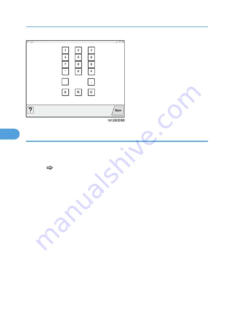
1. Touch
to select DRAM Test from the menu. The message "DRAM Test Testing…" displays. Then
the message "Resetting" Printer appears, and the power indicator light blinks red.
2. Turn the machine off and on. While the DRAM test executes, the power indicator blinks green.The
following type of message appears:
DRAM Test <### P:###### F:####
• xxx represents the installed DRAM size.
• P:###### represents the number of times the memory test has passed and finished
successfully. Initially 000000 displays with the maximum pass count being 999,999.
• F:##### represents the number of times the memory test has failed and finished with errors.
Initially 0000 displays with the maximum fail count being 99,999. Initially only four digits
appear, but additional digits appear as needed.
Each time a test is completed, the number of pass and failures increments. If the test fails, the
message "Failure" displays for approximately three seconds, and the failure count increases by
one.
The test continues until all standard and optional DRAM is tested. Once the maximum pass count or fail
count is reached, the test is stopped, the power indicator is turned on solid, and the final results display.
To stop the test before completion, turn the machine off.
5. System Maintenance
166
5
Summary of Contents for LI-MF1 M126
Page 1: ...Model LI MF1 Machine Codes M126 M127 M128 Field Service Manual 26 August 2011 ...
Page 2: ......
Page 3: ...Safety Notices The following laser notice labels may be attached to this machine 1 ...
Page 4: ...2 ...
Page 5: ...3 ...
Page 6: ...4 ...
Page 7: ...5 ...
Page 8: ...6 ...
Page 9: ...7 ...
Page 10: ...8 ...
Page 17: ...XPS XML Paper Specification 15 ...
Page 29: ...M Auto compensator Overview 27 1 ...
Page 30: ...Main Boards Controller Board 1 Product Information 28 1 ...
Page 37: ...2 Installation Installation Refer to the User s Guide 35 2 ...
Page 38: ...2 Installation 36 2 ...
Page 51: ...2 Remove the three screws B securing the top of the controller shield Removal Procedures 49 4 ...
Page 59: ...6 Remove the screw D from the gear E 7 Remove the plastic bushing F Removal Procedures 57 4 ...
Page 142: ...4 Replacement and Adjustment 140 4 ...
Page 192: ...5 System Maintenance 190 5 ...
Page 198: ...Symptom Action Fax reception fails p 276 Fax Reception Service Check 6 Troubleshooting 196 6 ...
Page 298: ...6 Troubleshooting 296 6 ...
Page 302: ...7 Energy Saving 300 7 ...
Page 303: ...Model LI MF1 Machine Codes M126 M127 M128 Appendices 12 October 2011 ...
Page 304: ......
Page 306: ...2 ...
Page 322: ...1 Appendix Specifications 18 1 ...
Page 324: ...MEMO 20 EN ...


