Beijing RichAuto S&T Co., Ltd.
19
on the real assembly position of HOME switches on the machine tool. If home switch is installed
in the positive movement direction, then home direction should set as “
Positive
”, if it is installed
in the negative movement direction, the home direction shall set as “
Negative
”.
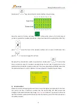
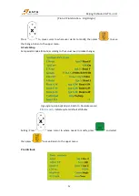
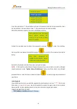
Setting mode: Enter“
Home direction
”, press “
” and move cursor as required.Press
“
”to change home direction, then press“
”to save the changes. Return to
“
Home direction
” menu.
Acceleration (Unit: mm/s
2
)
The maximum acceleration value during acceleration and deceleration movement, improve
(including straight and curved motion) processing capabilities. If acceleration value is too big, it
may cause the motor losing steps, tremble and even squeak; Setting value too small, will cut
down the operating speed of the entire graph.
System default: linear acceleration is 800 mm/s
2
, curve acceleration is 1000mm/s
2
, the proposed
curve acceleration is 1-1.5 times of the linear acceleration value.
Start Speed (Unit: mm/min)
Start speed of motion axis from stationary state. Not starting from 0, but starting directly from a
certain speed, so it can shorten the overall processing time, but this speed shouldn’t be too high.
Too high, it will cause the motor losing steps, jitter and even whistle; Set too small, it will reduce
the operating speed of the entire graph.
If the inertia of motion axes is heavy (shaft very heavy), can set a smaller starts peed; if the
inertia of motion axes is light (shaft very light), can increase the start speed value.
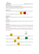
Voltage Setup
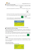
Used to set the input, output signal port normally open or normally closed port state, system
defines “
↓
” as normal open; “
↑
” as normal closed.
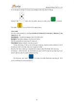
Including 2 rows of arrows
:
The upper arrows indicate the input level definition
:
Set input signal terminal status definition.
The first four:
0,1,2,3
are
X
axis ZERO
、
Y
axis ZERO
、
Z
axis ZERO
、
tool setting signal; The 5 to 8
positions are:
4,5,6,7
correspond driver alarm, hard limit, E-stop signal and foot switch input
signals.
The under arrows indicate the output level definition
:
Set output signal terminal status definition.
The top four: 0
、
1
、
2
、
3 correspond to
spindle On/Off
,
multi-speed 1
,
multi-speed 2
,
multi-speed
3
output signals; The 5 to 6 positions are:
4, 5
correspond
alarm lamp, run lamp
output signals.


