background image

13795-101 Rev. F

13

Installation, Features, & Functions

 (continued)

Articulating Wall Mount

 (continued)

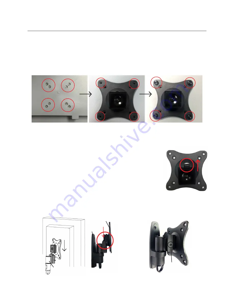
Attaching the ClearChart 4 to the Mount

1.  Align the half of the mount that was removed in the previous steps to the back of the ClearChart 

4, aligning it with the screw holes.  Refer to Figure SU-10.

Figure SU-10  Align Holes and Attach Mount

Screw 

Holes

Align Outer 

Holes

Install 

Thumb Screws

Note:

  There is a slot on the back of the mount.  Be sure this slot remains in the vertical position when 

aligning the mount to the back of the ClearChart 4.  Refer to Figure SU-11. 

2.  Using the Thumb Screws, secure the mount to the ClearChart 4 by 

hand-tightening the 4 screws into the outer screw holes on the back of 

the case of the ClearChart 4.  Refer to Figure SU-10.

Note:

  The screws must make at least three full turns into the mounting hole 

and fit snugly into place.  Do not over tighten.  

3.  Slide the ClearChart 4 onto the mounting bracket that is already attached 

to the wall, so the square slides into the slot on the mount.  Refer to 

Figure SU-12.  

4.  Secure the mount by tightening the two small flathead screws on either 

side of the mount where the ClearChart 4 attached to the wall mount. 

Refer to Figure SU-13.  

Figure SU-11  Align 

Slot Vertically

Figure SU-12  Attach ClearChart 4 to Wall Mount

Slide 

Down

Side 

View

Attached to Wall

Back of ClearChart 4

Attached 

to Wall

Attached to 

ClearChart 4

Securing 

Screw

Figure SU-13  Securing Screws

Summary of Contents for AcuityChek

Page 1: ...ClearChart 4 4X AcuityChek Digital Acuity Systems User s Guide...

Page 2: ...without notice Reichert Inc reserves the right to make changes in the product described in this manual without notice and without incorporating those changes in any products already sold ISO 13485 Ce...

Page 3: ...t Digital Refraction System 17 Bluetooth Connection 17 Remote Control Power 19 Remote Control Layout 19 Configuring the ClearChart 4 20 Optotypes 23 Size Progressions 24 Remote Control Functions 25 Vi...

Page 4: ...CTRIC SHOCK THIS EQUIPMENT MUST ONLY BE CONNECTED TO A SUPPLY MAINS WITH PROTECTIVE EARTH OR DAMAGE TO THIS INSTRUMENT AND OR INJURY TO THE OPERATOR OR PATIENT MAY OCCUR WARNING ENSURE THAT THE VOLTAG...

Page 5: ...OF THIS INSTRUMENT AS DAMAGE TO THE UNIT MAY OCCUR SEE MAINTENANCE SECTION FOR DETAILED CLEANING INSTRUCTION CAUTION USE OF AMMONIA BASED CLEANERS ON THE LIQUID CRYSTAL DISPLAY LCD MAY CAUSE DAMAGE T...

Page 6: ...ure Manufacturer Waste of Electrical and Electronic Equipment Compliance to Medical Device Directive 93 42 EEC Authorized to mark given by Intertek ETL Semko for conformance with electrical standards...

Page 7: ...of your new instrument Properly trained eyecare professionals such as ophthalmologists optometrists opticians and eye care technicians should operate this instrument Please retain this manual for futu...

Page 8: ...13790 Remote Control P N 13762 Two AAA batteries P N 13950000 902 Power Cords P N WCBL10018 and P N 13375 409 or P N WCBL10027 and P N 13775 410 Articulating Wall Mount with Screws P N 13775 023 Inclu...

Page 9: ...first surface mirror is a useful space saving device to increase the patient testing distance when the room does not permit a direct throw arrangement Typically your ClearChart 4 will be positioned h...

Page 10: ...T PANEL DISPLAYS THE MAXIMUM LOAD CA PACITY IS 30 POUNDS WARNING IF MOUNTING TO A WALL OF WOOD STUD CONSTRUCTION BE SURE THAT MOUNTING BOLTS ARE ANCHORED TO THE CENTER OF THE STUDS WARNING ALWAYS HAVE...

Page 11: ...edge to edge stud finder is highly recom mended Use a level to draw a vertical line down the center of the stud Refer to Figure SU 06 3 Place the wall plate on the wall as a template and mark the cent...

Page 12: ...ad of the equipment and all attached hardware and components 1 Remove the part of the mount that attaches to the back of the ClearChart 4 from the part of the mount that attaches to the wall by slidin...

Page 13: ...ClearChart 4 by hand tightening the 4 screws into the outer screw holes on the back of the case of the ClearChart 4 Refer to Figure SU 10 Note The screws must make at least three full turns into the...

Page 14: ...fer to Figure SU 14 Figure SU 14 Angling Bracket 120 15 Maintenance Once you have mounted the bracket and the ClearChart 4 check that they are secure and safe to use Check that the screws are fixed we...

Page 15: ...the refraction distance meets the requirements for either Direct throw or Mirror Arrangement 2 Level the supplied Wall Mount Bracket P N 13750 008 with the metal tabs facing up and out on your wall an...

Page 16: ...ure SU 18 Power Cord and On Off Switch Power Cord On Off Switch Disconnection of Input Power At any time the power switch can be set to OFF The unit does not have a power down sequence To terminate op...

Page 17: ...le or wirelessly connected using a Bluetooth serial adapter Wired communication between the ClearChart 4 and the digital refraction system requires connection of a cable between the serial port on the...

Page 18: ...nect the other end of the Null Modem Cable to the port on the bottom of the ClearChart 4 If using the USB Power Adaptor connect it to the USB port on the bottom Refer to Figure SU 22 Figure SU 22 Conn...

Page 19: ...W Function depends on test chart RIGHT ARROW Function depends on test chart LEFT ARROW Function depends on test chart DOWN ARROW Function depends on test chart MENU Menu options and settings SAVE Save...

Page 20: ...LEFT RIGHT arrows on your remote select DIRECT THROW or MIRRORED based on the configuration of your office When you are finished press the DOWN arrow UNITS Using the LEFT RIGHT arrows on your remote s...

Page 21: ...to the screen Press the DOWN arrow after each distance is entered OPTOTYPES Using the LEFT RIGHT arrows on your remote select the default optotype you would like the ClearChart 4 to display when firs...

Page 22: ...MIN and MAX to adjust green to desired tone Next press the DOWN arrow to enable adjustment of the red tone for the suppression letters MIN and MAX buttons will again change the color tone Press the RI...

Page 23: ...his set have been shown to be equivalent to the Landolt C Because of this each letter is essentially equally leg ible to patients Unlike the seventeen letter set no letter is easier or harder to ident...

Page 24: ...her line size progression available in ClearChart 4 is the LogMAR progression This progression has proved useful in prescribing low vision magnification aids and permits a more pre cise method of scor...

Page 25: ...ding size will be displayed A third press of this button will return you to normal lines of optotypes Note At larger optotype sizes there will be a limit of how many lines can be displayed This button...

Page 26: ...IGHT arrow button Pressing the RIGHT arrow button will randomize the optotypes on the screen The RIGHT arrow button is also used to select options during the initial setup of the ClearChart 4 as well...

Page 27: ...ed Installation Features Functions continued Remote Control Functions continued Menu Item Options 1 NOTATION Snellen Metric Decimal 2 DEFAULT OPTOTYPE 17 Letter Set 8 Letter Set ETDRS Sloan Tumbling E...

Page 28: ...ht corner displays the frequency and in the lower left the contrast level by percentage Pressing the CONT a second time exits this mode Note Contrast adjustment is only available in the ClearChart 4X...

Page 29: ...OWN arrow buttons to rotate the dial and adjust the angle T Pressing the T button will present an Astigmatic T Pressing the T button a second time will leave the Astigmatic T mode Use the UP and DOWN...

Page 30: ...ity test Press the HDISP button a second time for a second type of horizon tal disparity test Use the UP and DOWN arrow buttons to move the fixation line HDISP Press the HDISP button a third time for...

Page 31: ...on a second time to present closer bars A third press of the CBAR button will remove the bars OPTO You can change the optotype within the CBAR mode by pressing the OPTO button Use the UP DOWN arrows t...

Page 32: ...he Movie button Two selections will be presented on the display Video Files Video List To import a video select Video Files using the right arrow button on the remote Insert a USB drive with the desir...

Page 33: ...d Images Importing and Accessing Image Files Press the Menu button and then the EDU button The display will indicate three options Image Files Image List Screen Saver Logo To import new images select...

Page 34: ...ed but cannot be deleted from the image file list Changing the Screen Saver Insert the USB drive that contains the new screen saver logo into one of the USB ports on the bottom of the instrument The s...

Page 35: ...iod is reached Restoring the Default Screen Saver Go to the image management menu using the MENU and EDU buttons and select the Screen Saver Logo option Press the Right arrow button to select the Defa...

Page 36: ...with a lens cleaner that is safe for plastic lenses Refer to Figure MM 01 Fuse Replacement WARNING DISCONNECT POWER BEFORE ATTEMPTING TO REMOVE THE FUSES OR SERIOUS INJURY OR DEATH MAY OCCUR Replace...

Page 37: ...n Not plugged into an outlet with power Plug unit into a properly volted outlet Power cord not fully pushed into the power input receptacle Fully install power cord Fuse s is blown Replace the fuse s...

Page 38: ...Temperature 20 C 4 F to 50 C 122 F Relative Humidity 10 to 80 non condensing Atmospheric Pressure 70 20 7 in Hg to 106 kPa 31 3 in Hg Exposure to extreme temperature conditions indicated above must no...

Page 39: ...hock particularly regarding allowable leakage currents and reliability of the protective earth connection No applied parts per the noted standards The ClearChart 4 is classified as IPX0 Equipment IPX0...

Page 40: ...interference in nearby electronic equipment Harmonics IEC 61000 3 2 Class A The ClearChart 4 is suitable for use in all establish ments including domestic establishments and those directly connected t...

Page 41: ...0 4 2 Floors should be wood concrete or ceramic tile If floors are synthetic the r h should be at least 30 2kV 4kV 8kV Contact 2kV 4kV 8kV 15kV Air 2kV 4kV 8kV Contact 2kV 4kV 8kV 15kV Air Compliance...

Page 42: ...uipment marked with the following symbol Radiated RF IEC 61000 4 3 80 MHz to 2 7 GHz 3V m 80 MHz to 2 7 GHz 10V m E1 3 V m E1 10 V m Note 1 At 80 MHz and 800 MHz the higher frequency range applies Not...

Page 43: ...ccording to the maximum output power of the communications equipment Max Output Power of Trans mitter W Separation m 150kHz to 80 MHz d 3 5 V1 Sqrt P Separation m 80 to 800 MHz d 3 5 E1 Sqrt P Separat...

Page 44: ...tion distance calculated from the equation ap plicable to the frequency of the transmitter Recommended Separa tion Distance d 6 E Sqrt P Where P is the maxi mum power in watts d is the minimum separat...

Page 45: ...Module Protocol Bluetooth Frequency Band 2 4020 2 4800 GHz Modulation Method GFSK Basic Mode 4 DQPSK 8 DPSK EDR Mode Channel Access Protocol FHSS Frequency Hopping Spread Spectrum RF Output Power Cla...

Page 46: ...CALELECTRICALEQUIPMENTUSEDWITHTHECLEARCHART4MUSTBECOMPLI ANT WITH AN APPLICABLE IEC OR ISO SAFETY STANDARD Cable Reference Length Description 16200 440 11m 35ft DB9 M F Null Modem Cable shielded Any 1...

Page 47: ...ling of the product Patent Warranty If notified promptly in writing of any action brought against the purchaser based on a claim that the instrument infringes a U S Patent Reichert will defend such ac...

Page 48: ...686 4555 Email reichert information ametek com www reichert com Authorized European Representative AMETEK GmbH Business Unit Reichert Carl von Linde Strasse 42 85716 Unterschleissheim Munich Germany...

Reviews: