


Determining Hardware Status
Determining Operating Status
5-5
Determine the Status of Ethernet Management and Copper FE MIC Ports
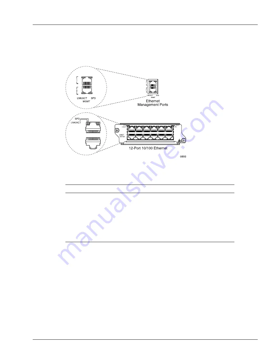
Figure 5-4 shows the facility LEDs for the Ethernet management and copper FE MIC ports.
Figure 5-4
LEDs on the Ethernet
Management and Copper FE MIC Ports
Table 5-2 lists the facility LEDs for the Ethernet management and copper FE MIC ports.
Table 5-2
Facility LEDs for Ethernet Management and Copper FE MIC Ports
Label
Activity
Color
Description
LNK/ACT
On
Green
The port is up.
Blinking
Green
The port is receiving or transmitting frames.
Off
None
The port is down.
SPD
On
Green
The Ethernet management port is operating at 1000 Mbps.
On
Yellow
The port is operating at 100 Mbps.
Off
None
The port is operating at 10 Mbps.
Summary of Contents for SmartEdge 100
Page 4: ......
Page 8: ...viii SmartEdge 100 Router Hardware Guide...
Page 14: ...Ordering Documentation xiv SmartEdge 100 Router Hardware Guide...
Page 52: ...Connecting and Routing the Cables 4 18 SmartEdge 100 Router Hardware Guide...
Page 72: ...Obtaining Assistance 5 20 SmartEdge 100 Router Hardware Guide...
Page 90: ...FE and GE MIC and Native Port Cables A 6 SmartEdge 100 Router Hardware Guide...
Page 94: ...FE and GE Port Alarms B 4 SmartEdge 100 Router Hardware Guide...