


Connecting the Power Cables
4-10
SmartEdge 100 Router Hardware Guide
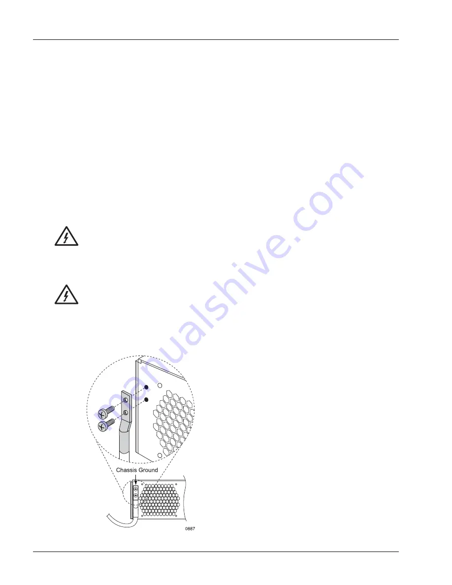
Connect the Chassis Ground Cable
The back panel of the SmartEdge 100 chassis has a pair of M5 screws, which are used to attach a ground
cable, at the upper left corner of the chassis rear panel.
The ground cable must be of a size suitable for the installation (#4 AWG standard copper), and must be
installed in accordance with the National Electrical Code (in the United States), or the applicable local
jurisdiction (outside the United States) installation requirements.
To connect the chassis ground cable, perform the following steps (see Figure 4-6):
1. Using a crimping tool, attach a two-hole lug to one end of the ground cable.
2. Using a Phillips screwdriver, remove the pair of M5 screws.
3. Place the two-hole lug over the screw holes and insert the screws in the screw holes.
4. Using the Phillips screwdriver, tighten the screws using 15.0 inch-lbs torque (1.7 Newton-meters)
maximum.
5. Connect the other end of the cable to an appropriate ground point.
Figure 4-6
Ground Cable Connection
Warning
Risk of electrical shock. The system uses DC power sources, which can cause severe injury. To
reduce the risk, the DC power sources must be installed only in restricted access areas
(dedicated equipment rooms, equipment closets, or the like) in accordance with Articles
110-17, 110-26, and 110-27 of the National Electric Code, ANSI/NFPA 70. Connect the chassis
to a –48 VDC source that is reliably connected to earth.
Warning
Risk of electrical shock. Because a system is fully powered on after all power connections are
made, it can cause shock if a power cable is disconnected from the chassis. To reduce the risk,
a readily accessible disconnect device, such as a fuse in a fuse panel, must be provided in the
fixed wiring for each DC power source. It must be suitable for the rated voltage and current
specified.
Summary of Contents for SmartEdge 100
Page 4: ......
Page 8: ...viii SmartEdge 100 Router Hardware Guide...
Page 14: ...Ordering Documentation xiv SmartEdge 100 Router Hardware Guide...
Page 52: ...Connecting and Routing the Cables 4 18 SmartEdge 100 Router Hardware Guide...
Page 72: ...Obtaining Assistance 5 20 SmartEdge 100 Router Hardware Guide...
Page 90: ...FE and GE MIC and Native Port Cables A 6 SmartEdge 100 Router Hardware Guide...
Page 94: ...FE and GE Port Alarms B 4 SmartEdge 100 Router Hardware Guide...