


Connecting and Routing the Cables
Installing the Hardware
4-17
2. Connect and route the management access cables, depending on the type of management access you
have selected, and the cables for the native ports; see Figure 4-10 for connecting a management
workstation and Figure 4-11 for connecting a local or remote console. Perform the following steps:
a. Thread the system ends of the system management and native port cables through the cable
management bracket at the left side of the chassis.
b. Insert each cable in the appropriate connector on the front panel.
c. Tie-wrap the cables to form a bundle, and then tie each bundle to the cable bracket.
3. Connect and route the cables for the MIC ports. Perform the following steps:
a. Thread the system ends of the MIC cables through the cable management bracket at the right side
of the chassis.
b. Insert each cable in the appropriate connector on the MIC front panel.
c. Tie-wrap the cables from each MIC to form a bundle, and then tie each bundle to the cable bracket.
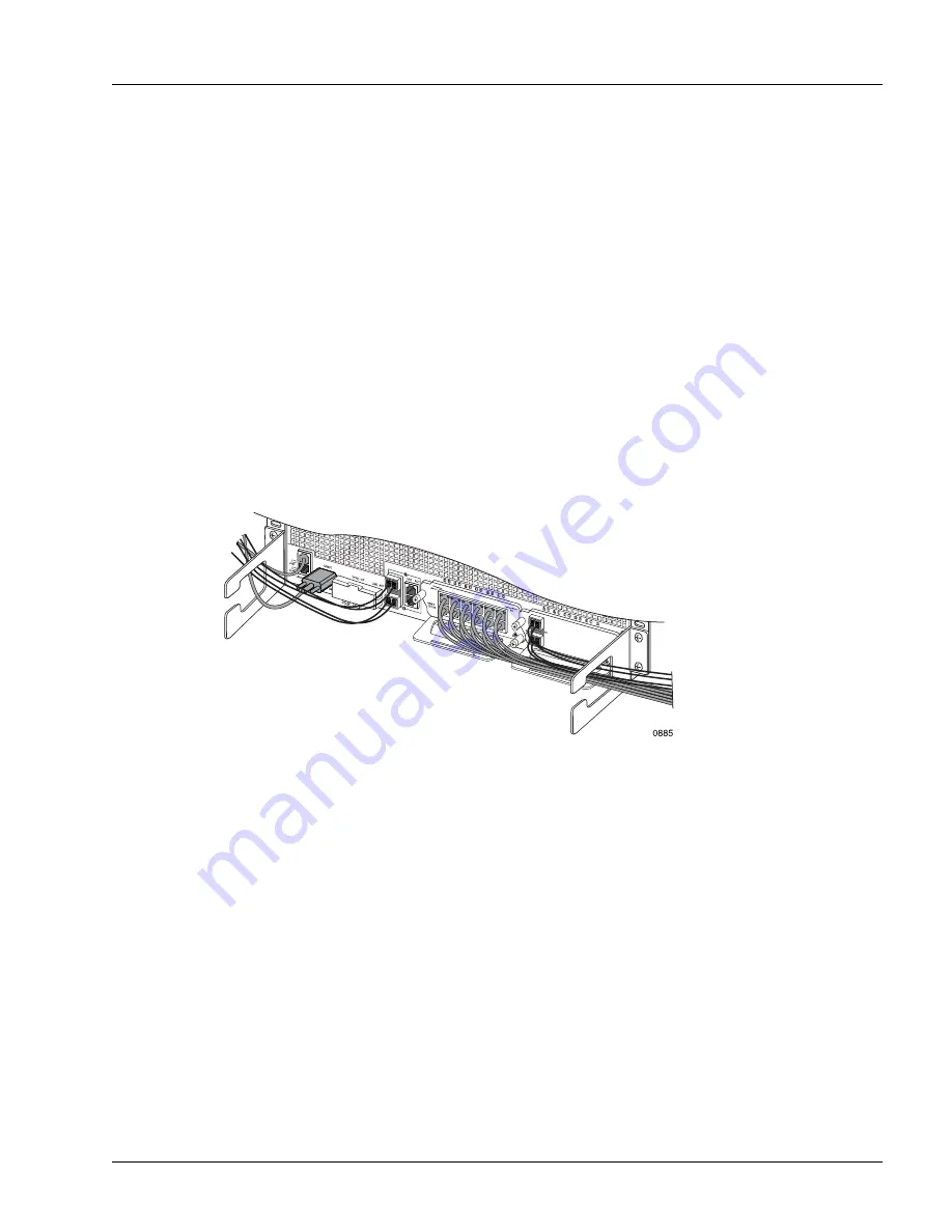
For an example of connected and routed cables, see Figure 4-12.
Figure 4-12 Cable Routing
Connect the Equipment and Network Ends of the Cables
To connect the equipment and network ends of the cables, perform the following steps:
1. Connect the MIC cables to their networks.
2. Ensure that the management access equipment is configured properly according to the specifications
given in the “Selecting the Type of Management Access” section in Chapter 3, “Preparing for
Installation.”
3. Connect the management access cables to the equipment or their networks; perform this step for one or
more of these options, depending on the cables you have connected to the system:
•
Management workstation; see Figure 4-10 on page 4-15.
•
Console terminal; see Figure 4-11 on page 4-16.
You are now ready to power on the system and check the operating status; continue with Chapter 5,
“Determining Operating Status.”
Summary of Contents for SmartEdge 100
Page 4: ......
Page 8: ...viii SmartEdge 100 Router Hardware Guide...
Page 14: ...Ordering Documentation xiv SmartEdge 100 Router Hardware Guide...
Page 52: ...Connecting and Routing the Cables 4 18 SmartEdge 100 Router Hardware Guide...
Page 72: ...Obtaining Assistance 5 20 SmartEdge 100 Router Hardware Guide...
Page 90: ...FE and GE MIC and Native Port Cables A 6 SmartEdge 100 Router Hardware Guide...
Page 94: ...FE and GE Port Alarms B 4 SmartEdge 100 Router Hardware Guide...