RED DSMC OPERATION GUIDE
COPYRIGHT © 2013 RED.COM, INC
955-0020_V5.1, REV-D
|
27
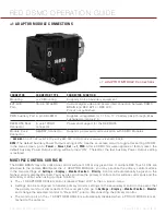
+1 ADAPTOR MODULE CONNECTIONS
CONNECTOR
CONNECTOR TYPE
CONNECTOR FUNCTION
Mounting
¼-20 Mounting
Supports bolt-on auxiliary equipment
EVF/LCD
Port
1
16-pin 1B LEMO
Custom digital video and power interconnection between DSMC
BRAIN and RED EVF or RED LCD;
Pinout not published
PWR Auxiliary Port 4-pin 0B LEMO
Supplies unregulated (+) 11.5 to 17 V battery pass-through; Max
sustained current is 2 A
REDMOTE Dock
Connector
8-point POGO
connector
Power and support for the REDMOTE
Module Dock
Connector
SEARAY Connector
Supports power and communication with DSMC Modules
1.
WARNING:
DO NOT USE the EVF/LCD port if a RED PRO I/O MODULE is connected to the DSMC BRAIN.
NOTE:
The default Auxiliary Power Output setting is ON. Use the on-screen menu to toggle this setting ON/OFF.
In the menu screen, go to:
Power
>
Power_Out
>
+1_PWR
. After a DSMC firmware upgrade or factory reset, the
default Auxiliary Power Output setting will be turned “ON”. Thereafter, the last Auxiliary Power Output setting
is restored.
MULTIPLE CONTROL SURFACES
The DSMC BRAIN may only utilize one control surface (LCD) at any given time. If multiple RED Touch LCDs are
attached to the camera BRAIN and the +1 ADAPTOR MODULE, you may prioritize the primary control surface
in the menu settings at:
Settings
>
Display
>
Monitor Control
>
Priority
. Control will automatically be given to the
highest priority display attached. You may also prioritize the primary monitor control surface commands and the
secondary monitor when using multiple monitors.
The +1 ADAPTOR MODULE monitor is labeled “Rear LCD” in the on-screen menu.
Settings can be configured to transfer primary monitor settings to the secondary monitor in the event that
the primary monitor is disconnected. To accomplish this, go to
Settings
>
Display
>
Monitor Control
>
Monitor
and change the selected monitor to “Rear LCD” prior to disconnecting the primary monitor.
The monitor port on the +1 ADAPTOR MODULE is automatically disabled when a PRO I/O MODULE is at-
tached to the camera.
+1 ADAPTOR MODULE Connections
Summary of Contents for Dragon
Page 1: ...EPIC SCARLET V5 1 DRAGON MYSTERIUM X RED COM RED DSMC O PERAT ION GU IDE ...
Page 161: ...RED DSMC OPERATION GUIDE COPYRIGHT 2013 RED COM INC 955 0020_V5 1 REV D 161 SIDE VIEW ...
Page 162: ...COPYRIGHT 2013 RED COM INC RED DSMC OPERATION GUIDE 955 0020_V5 1 REV D 162 TOP VIEW ...
Page 163: ...RED DSMC OPERATION GUIDE COPYRIGHT 2013 RED COM INC 955 0020_V5 1 REV D 163 BOTTOM VIEW ...
Page 164: ...COPYRIGHT 2013 RED COM INC RED DSMC OPERATION GUIDE 955 0020_V5 1 REV D 164 BACK VIEW ...


