Switching on the AIS receiver —
Ray70
The
Ray70
’s AIS receiver can be switched on or off.
From the Main menu:
1. Select
Set-up
.
2. Select
AIS
.
3. Select
On
.
Selecting a network type
When connecting your radio to other devices it is
important to ensure you select the network connection
and type that you want data to be transmitted over.
From the Main menu:
1. Select
Set-up
.
2. Select
Network output
.
The following network types are available:
•
NMEA 2000 (default)
•
0183 High speed
•
0183 Std speed
3. Select the network type relevant to the devices
connected to your radio. If your radio is not
connected to any other devices any option can be
selected.
Selecting
0183 Std speed
will disable the internal
AIS receiver on a
Ray70
.
The
Network output
setting determines the baud rate
of the
NMEA 0183
input:
Network output setting
NMEA 0183 input baud rate
NMEA 2000
Standard speed (4800)
NMEA 0183 High Speed
High speed (38400)
NMEA 0183 Standard Speed
Standard speed (4800)
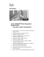
Entering your MMSI number
To program your radio with your MMSI number follow
the steps below.
D13224-1
1
2
3
4
From the Main menu:
1. Select
Set-up
.
2. Select
DSC set-up
.
3. Select
MMSI
.
(Not set)
will be displayed if no MMSI number has
been set.
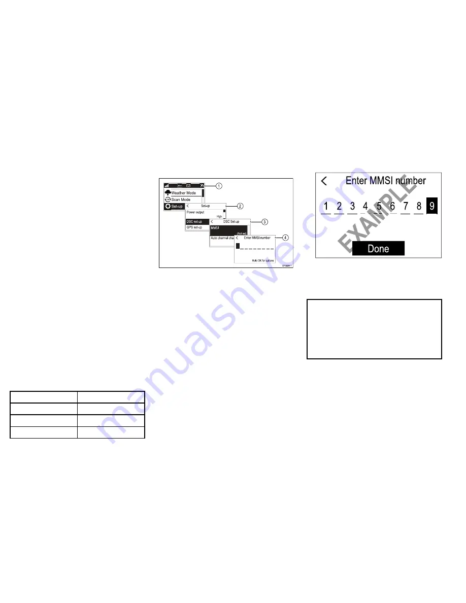
4. Use the
Rotary knob
to cycle through the available
numbers and press
OK
to confirm each number and
move to the next digit.
You should only enter the unique 9 digit MMSI
number provided by your licensing authority.
MMSI numbers starting with a ‘0’ are only used for
groups and coast stations. If you enter a ‘0’ as the
first digit the radio will assume you are entering a
coast station MMSI and automatically assign a ‘0’ as
the second digit; this is to ensure a group MMSI is
not entered as the radio’s unique MMSI.
5. Press the
Back
button at any time to edit digits you
have already entered.
6. Press and hold the
OK
button to display options to
Move cursor
back and forward through the digits.
7. When the final digit is confirmed select
DONE
.
Example
Enter MMSI number
9
8
7
6
5
4
3
2
1
Done
E
XA
M
PL
E
Enter MMSI number
EX
AM
PL
E
EX
AM
PL
E
EX
AM
PL
E
6
5
EX
AM
PL
E
8. The MMSI is displayed onscreen, check that it is
correct, then:
i.
Select
Yes – Save
, or
ii. if the number entered is not correct select
No
– Retry
.
Caution: MMSI and ATIS ID
entry
You can only enter the MMSI number and
ATIS ID once!
If you store an incorrect MMSI number or
ATIS ID in your product, it will have to be
reset by an authorized
Raymarine
®
dealer.
Enabling and disabling ATIS
mode
ATIS is a European system used on some inland
waterways. ATIS must be enabled and a unique ATIS
ID entered in order to use ATIS mode.
From the Main menu.
1. Select
Set-up
.
2. Select
ATIS set-up
.
20
Ray52 / Ray50 / Ray60 / Ray70