background image

(which may be grounded). A protective boot is supplied
that can be used to ensure isolation of the antenna
connection.

1

3

2

4

5

6

D13235-1

1. Disconnect your antenna cable from the connector.

2. Push the antenna cable through the supplied

protective boot.

3. Re-connect the antenna cable to the connector.

4. Plug the antenna connector into the product’s

antenna connection and secure by tightening the
locking collar.

5. Push the protective boot over the connection.

6. Secure the protective boot using the supplied cable

ties.

If the antenna connector cannot be removed then
another suitable means of protection must be used,
such as electrical tape.

Controls and interface

The controls and interface available are as follows:

Base station

D13220-1

5

6

7

8

1

3

2

4

1.

Built-in speaker

2.

Rotary knob / OK push button

— Press knob in

to access menu / DSC functions and to confirm
selections. Turn rotary clockwise or anti-clockwise
to move up and down through menu items or to
change channel from the Homescreen.

3.

LCD

4.

VOL/SQ

— Turn knob to adjust volume or squelch

up and down. Press center button to switch
between volume and squelch control.

5.

DISTRESS

— Push up the spring loaded cover and

press this button to make a DSC distress call.

6.

16 / PLUS

— When powered on press to switch

between priority channels.

7.

Power

— Press to power the unit on. Press and

hold for 3 seconds to power the unit off. Momentary
press to access the shortcut list.

8.

Back

— Move back through menu options.

Fistmic

D13221-1

2

1

6

4

3

5

1.

PTT (Push to Talk)

— Press and hold to send a

voice message. Release to return to receive mode.

Note:

The maximum transmit time is limited

to 5 minutes to prevent un-intentional
transmissions from occupying the VHF
channel.

2.

Speaker

3.

Microphone location

4.

Channel Up and Down

— Changes the channel

up or down.

5.

HI/LO

— Press to switch between High (25 W) and

low (1 W) transmit power.

6.

16 / PLUS

— When powered on press to switch

between priority channels.

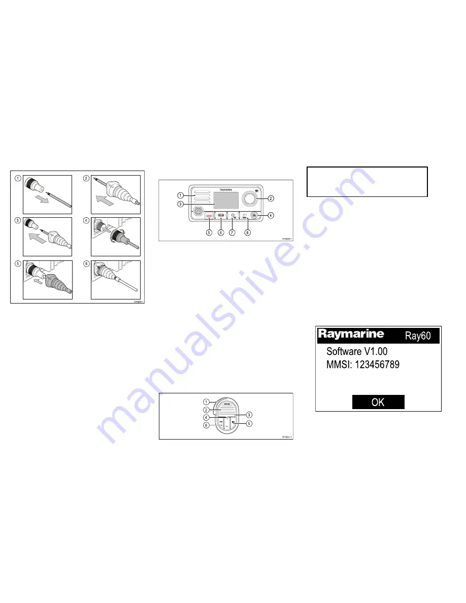
Powering the unit on

With the radio connected to a power supply the power
button is used to switch the radio on and off.

1. Press the

Power

button to power-up the radio.

The startup is displayed.

Ray60

Software V1.00

MMSI: 123456789

O

K

The startup screen will automatically time-out after
5 seconds.

2. Press the

OK

button, or wait for the startup screen

to time-out.

16

Ray52 / Ray50 / Ray60 / Ray70

Summary of Contents for RAY50

Page 1: ...Mounting and Getting Started ENGLISH Date 01 2016 Document number 88033 3 EN 2016 Raymarine UK Limited Ray50 Ray52 Ray60 Ray70 Ray52 Ray50 Ray60 Ray70...

Page 2: ...ENGLISH Date 01 2016...

Page 3: ...e bearing and distance from a known point I am state nature of distress e g sinking on fire etc I have state number of persons on board and any other information drifting flares fired etc I REQUIRE IM...

Page 4: ...io operator s responsibility to ensure that no one comes within this radius For optimal radio performance and minimal human exposure to radio frequency electromagnetic energy make sure the antenna is...

Page 5: ...2 This device must accept any interference including interference that may cause undesired operation of the device This Class B digital apparatus complies with Canadian ICES 003 Industrie Canada Fran...

Page 6: ...nts of the Regional Arrangement on the Radiocommunication Service for Inland Waterways also known as RAINWAT ATIS adds data at the end of radio transmissions that identifies your station ATIS operatio...

Page 7: ...t www raymarine com Product disposal Dispose of this product in accordance with the WEEE Directive The Waste Electrical and Electronic Equipment WEEE Directive requires the recycling of waste electric...

Page 8: ...r vessels it may not be possible to locate the product this far away from a compass In this situation when choosing the installation location for your product ensure that the compass is not affected b...

Page 9: ...sure that cables that are not connected are protected NEVER leave bare ended wires uncovered unprotected as this could cause a short circuit and can induce galvanic corrosion Electrical interference S...

Page 10: ...roduct on it s bracket Before mounting the unit ensure that you have Selected a suitable location ensuring there is nothing behind the mounting surface that may be damaged when drilling Identified the...

Page 11: ...D13207 1 1 Check the selected location for the unit A clear flat area with suitable clearance behind the panel is required 2 Fix the supplied mounting template to the selected location using masking o...

Page 12: ...mplate to accept the fixings 7 Remove the backings from the supplied gasket 8 Place the gasket in position on the back of the unit and press firmly onto the flange 9 Connect the power and other cables...

Page 13: ...Note Drill bit tap size and tightening torque is dependent on the thickness and type of material the unit is to be mounted on Power connection The power supply should be connected as shown below 12 v...

Page 14: ...e Note The suitable fuse rating for the thermal breaker is dependent on the number of devices you are connecting If in doubt consult an authorized Raymarine dealer Your product s power cable may have...

Page 15: ...g collar anti clockwise to the unlocked position 2 Ensure the spur cable connector is correctly orientated 3 Fully insert the spur cable connector into the SeaTalkng connector on the unit 4 Rotate the...

Page 16: ...n Press center button to switch between volume and squelch control 5 DISTRESS Push up the spring loaded cover and press this button to make a DSC distress call 6 16 PLUS When powered on press to switc...

Page 17: ...the a suffix b Indicates that the channel is a receive only channel Used for Canadian channels only Note You cannot transmit on a receive only channel 5 Channel Indicates the current channel number 6...

Page 18: ...23 1 1 Currently selected menu item 2 Scroll bar 3 Menu items The main menu includes the following items Symbol Name Sub options DSC Calls Individual call Distress call Position request Group call All...

Page 19: ...y applicable to radios with a built in AIS receiver See Switching on the AIS receiver for more information 3 Select network type Selects which connection to transmit AIS and DSC information to connect...

Page 20: ...ailable numbers and press OK to confirm each number and move to the next digit You should only enter the unique 9 digit MMSI number provided by your licensing authority MMSI numbers starting with a 0...

Page 21: ...bers and press OK to confirm each number and move to the next digit You should only enter the unique 10 digit ATIS ID provided by your licensing authority 6 Press the Back button at any time to edit d...

Page 22: ...l 1 Press the 16 PLUS button 2 Press and hold the PTT button 3 Slowly and clearly speak the details of the distress MAYDAY MAYDAY MAYDAY This is state name of vessel 3 times MAYDAY state name of vesse...

Page 23: ...d to relay the distress to a CRS by any means possible Class D DSC radios are forbidden from automatically acknowledging distress calls Acknowledgement must only be made by voice message on channel 16...

Page 24: ...24 Ray52 Ray50 Ray60 Ray70...

Page 25: ......

Page 26: ...www raymarine com Ray52 Ray50 Ray60 Ray70...

Reviews: