background image

Making a distress call

In an emergency you can use your unit to make an
automatic DSC distress call.

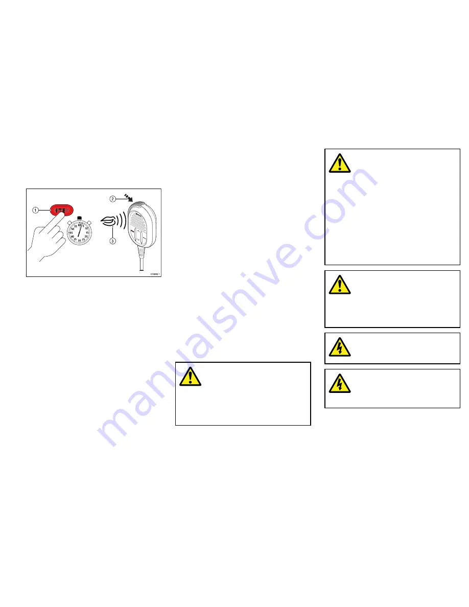
With the spring loaded cover open:

1

0

15

20

25

30

35

40

45

50

55

60 5

3

1

2

D13202-1

1. Press and hold the

DISTRESS

button for 3 seconds.

Once the

DISTRESS

button is pressed a 3 second

count down will begin, when the count down reaches
zero the DSC distress call is transmitted.

The distress call is repeated automatically until it is
acknowledged.

2. Press and hold the

PTT

button, then slowly and

clearly speak the details of the distress in the
following format:

MAYDAY, MAYDAY, MAYDAY

This is

<state name of vessel 3 times>

MAYDAY

<state name of vessel 1 time>

My position is

<state latitude and longitude, or true

bearing and distance from a known point.>

I am

<state nature of distress e.g. sinking, on fire

etc.>

I have

<state number of persons on board and any

other information — drifting, flares fired etc.>

I REQUIRE IMMEDIATE ASSISTANCE

OVER

3. Release the

PTT

button.

Making a Mayday call

In an emergency you can use your unit to make a
Mayday call.

1. Press the

16 PLUS

button.

2. Press and hold the

PTT

button.

3. Slowly and clearly speak the details of the distress:

MAYDAY, MAYDAY, MAYDAY

This is

<state name of vessel 3 times>

MAYDAY

<state name of vessel 1 time>

My position is

<state latitude and longitude, or true

bearing and distance from a known point.>

I am

<state nature of distress e.g. sinking, on fire

etc.>

I have

<state number of persons on board and any

other information — drifting, flares fired etc.>

I REQUIRE IMMEDIATE ASSISTANCE

OVER

4. Release the

PTT

button.

5. If an acknowledgement is not received then repeat

steps 2 to 4 above.

Important information

Warning: Read the expanded
handbook

This document is a subset of the full
documentation for your product. For
the complete documentation and safety
information, please refer to the expanded
handbook, available on the Raymarine
website (

www.raymarine.com

).

Warning: Product installation
and operation

• This product must be installed and

operated in accordance with the
instructions provided. Failure to do so
could result in personal injury, damage
to your vessel and/or poor product
performance.

• Raymarine recommends certified

installation by a Raymarine approved
installer. A certified installation qualifies
for enhanced product warranty benefits.
Contact your Raymarine dealer for
further details, and refer to the separate
warranty document packed with your
product.

Warning: Potential ignition
source

This product is NOT approved for use in
hazardous/flammable atmospheres. Do
NOT install in a hazardous/flammable
atmosphere (such as in an engine room or
near fuel tanks).

Warning: 12 Volt dc only

This product must only be connected to a

12 volt dc

power source.

Warning: Positive ground
systems

Do not connect this unit to a system which
has positive grounding.

3

Summary of Contents for RAY50

Page 1: ...Mounting and Getting Started ENGLISH Date 01 2016 Document number 88033 3 EN 2016 Raymarine UK Limited Ray50 Ray52 Ray60 Ray70 Ray52 Ray50 Ray60 Ray70...

Page 2: ...ENGLISH Date 01 2016...

Page 3: ...e bearing and distance from a known point I am state nature of distress e g sinking on fire etc I have state number of persons on board and any other information drifting flares fired etc I REQUIRE IM...

Page 4: ...io operator s responsibility to ensure that no one comes within this radius For optimal radio performance and minimal human exposure to radio frequency electromagnetic energy make sure the antenna is...

Page 5: ...2 This device must accept any interference including interference that may cause undesired operation of the device This Class B digital apparatus complies with Canadian ICES 003 Industrie Canada Fran...

Page 6: ...nts of the Regional Arrangement on the Radiocommunication Service for Inland Waterways also known as RAINWAT ATIS adds data at the end of radio transmissions that identifies your station ATIS operatio...

Page 7: ...t www raymarine com Product disposal Dispose of this product in accordance with the WEEE Directive The Waste Electrical and Electronic Equipment WEEE Directive requires the recycling of waste electric...

Page 8: ...r vessels it may not be possible to locate the product this far away from a compass In this situation when choosing the installation location for your product ensure that the compass is not affected b...

Page 9: ...sure that cables that are not connected are protected NEVER leave bare ended wires uncovered unprotected as this could cause a short circuit and can induce galvanic corrosion Electrical interference S...

Page 10: ...roduct on it s bracket Before mounting the unit ensure that you have Selected a suitable location ensuring there is nothing behind the mounting surface that may be damaged when drilling Identified the...

Page 11: ...D13207 1 1 Check the selected location for the unit A clear flat area with suitable clearance behind the panel is required 2 Fix the supplied mounting template to the selected location using masking o...

Page 12: ...mplate to accept the fixings 7 Remove the backings from the supplied gasket 8 Place the gasket in position on the back of the unit and press firmly onto the flange 9 Connect the power and other cables...

Page 13: ...Note Drill bit tap size and tightening torque is dependent on the thickness and type of material the unit is to be mounted on Power connection The power supply should be connected as shown below 12 v...

Page 14: ...e Note The suitable fuse rating for the thermal breaker is dependent on the number of devices you are connecting If in doubt consult an authorized Raymarine dealer Your product s power cable may have...

Page 15: ...g collar anti clockwise to the unlocked position 2 Ensure the spur cable connector is correctly orientated 3 Fully insert the spur cable connector into the SeaTalkng connector on the unit 4 Rotate the...

Page 16: ...n Press center button to switch between volume and squelch control 5 DISTRESS Push up the spring loaded cover and press this button to make a DSC distress call 6 16 PLUS When powered on press to switc...

Page 17: ...the a suffix b Indicates that the channel is a receive only channel Used for Canadian channels only Note You cannot transmit on a receive only channel 5 Channel Indicates the current channel number 6...

Page 18: ...23 1 1 Currently selected menu item 2 Scroll bar 3 Menu items The main menu includes the following items Symbol Name Sub options DSC Calls Individual call Distress call Position request Group call All...

Page 19: ...y applicable to radios with a built in AIS receiver See Switching on the AIS receiver for more information 3 Select network type Selects which connection to transmit AIS and DSC information to connect...

Page 20: ...ailable numbers and press OK to confirm each number and move to the next digit You should only enter the unique 9 digit MMSI number provided by your licensing authority MMSI numbers starting with a 0...

Page 21: ...bers and press OK to confirm each number and move to the next digit You should only enter the unique 10 digit ATIS ID provided by your licensing authority 6 Press the Back button at any time to edit d...

Page 22: ...l 1 Press the 16 PLUS button 2 Press and hold the PTT button 3 Slowly and clearly speak the details of the distress MAYDAY MAYDAY MAYDAY This is state name of vessel 3 times MAYDAY state name of vesse...

Page 23: ...d to relay the distress to a CRS by any means possible Class D DSC radios are forbidden from automatically acknowledging distress calls Acknowledgement must only be made by voice message on channel 16...

Page 24: ...24 Ray52 Ray50 Ray60 Ray70...

Page 25: ......

Page 26: ...www raymarine com Ray52 Ray50 Ray60 Ray70...

Reviews: