background image

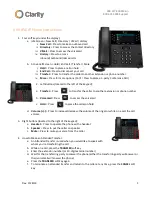
Distribution panel connection

It is recommended that your product is wired through
your vessel’s distribution panel via a thermal breaker
or fuse.

D13092-1

2

3

1

4

5

1.

Vessel power supply positive (+)

2.

In-line fuse. (If your product’s power cable does not
have an in-line fuse then one should be fitted.)

3.

Product power cable

4.

Vessel power supply negative (-)

5.

Vessel distribution panel
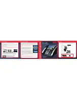
Battery connection

Your product may be wired directly to the battery using
an in-line fuse.

D13091-1

2

4

1

5

3

1.

Vessel power supply positive (+)

2.

Vessel power supply negative (-)

3.

In-line fuse. (If your product’s power cable does not
have an in-line fuse then one should be fitted.)

4.

Product power cable

5.

Vessel battery

In-line fuse and thermal breaker ratings

The following in-line fuse and thermal breaker ratings
apply to your product:

In-line fuse rating

Thermal breaker rating

10 A

7 A (if only connecting one
device)

Note:

• The suitable fuse rating for the thermal breaker

is dependent on the number of devices you are
connecting. If in doubt consult an authorized

Raymarine

®

dealer.

• Your product’s power cable may have fitted in-line

fuse, if not then you can add an in-line fuse to the
positive wire of your products power connection.
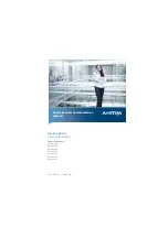
Sharing a breaker

Where more than 1 piece of equipment shares a
breaker you must provide protection for the individual
circuits. E.g. by connecting an in-line fuse for each
power circuit.

D11637-2

2

4

4

1

3

+

-

1

Positive (+) bar

2

Negative (-) bar

3

Circuit breaker

4

Fuse

Where possible, connect individual items of equipment
to individual circuit breakers. Where this is not possible,
use individual in-line fuses to provide the necessary
protection.

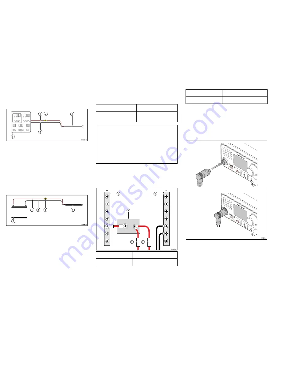
Connecting the Fistmic – Ray60 / Ray70

The Fistmic can be connected directly to the connector
on the front of the unit.

D13217-1

1. Ensure the Fistmic cable connector is correctly

orientated.

2. Fully insert the connector into the connector on the

front of the unit.

3. Rotate the locking collar clockwise until it clicks.

14

Ray52 / Ray50 / Ray60 / Ray70

Summary of Contents for RAY50

Page 1: ...Mounting and Getting Started ENGLISH Date 01 2016 Document number 88033 3 EN 2016 Raymarine UK Limited Ray50 Ray52 Ray60 Ray70 Ray52 Ray50 Ray60 Ray70...

Page 2: ...ENGLISH Date 01 2016...

Page 3: ...e bearing and distance from a known point I am state nature of distress e g sinking on fire etc I have state number of persons on board and any other information drifting flares fired etc I REQUIRE IM...

Page 4: ...io operator s responsibility to ensure that no one comes within this radius For optimal radio performance and minimal human exposure to radio frequency electromagnetic energy make sure the antenna is...

Page 5: ...2 This device must accept any interference including interference that may cause undesired operation of the device This Class B digital apparatus complies with Canadian ICES 003 Industrie Canada Fran...

Page 6: ...nts of the Regional Arrangement on the Radiocommunication Service for Inland Waterways also known as RAINWAT ATIS adds data at the end of radio transmissions that identifies your station ATIS operatio...

Page 7: ...t www raymarine com Product disposal Dispose of this product in accordance with the WEEE Directive The Waste Electrical and Electronic Equipment WEEE Directive requires the recycling of waste electric...

Page 8: ...r vessels it may not be possible to locate the product this far away from a compass In this situation when choosing the installation location for your product ensure that the compass is not affected b...

Page 9: ...sure that cables that are not connected are protected NEVER leave bare ended wires uncovered unprotected as this could cause a short circuit and can induce galvanic corrosion Electrical interference S...

Page 10: ...roduct on it s bracket Before mounting the unit ensure that you have Selected a suitable location ensuring there is nothing behind the mounting surface that may be damaged when drilling Identified the...

Page 11: ...D13207 1 1 Check the selected location for the unit A clear flat area with suitable clearance behind the panel is required 2 Fix the supplied mounting template to the selected location using masking o...

Page 12: ...mplate to accept the fixings 7 Remove the backings from the supplied gasket 8 Place the gasket in position on the back of the unit and press firmly onto the flange 9 Connect the power and other cables...

Page 13: ...Note Drill bit tap size and tightening torque is dependent on the thickness and type of material the unit is to be mounted on Power connection The power supply should be connected as shown below 12 v...

Page 14: ...e Note The suitable fuse rating for the thermal breaker is dependent on the number of devices you are connecting If in doubt consult an authorized Raymarine dealer Your product s power cable may have...

Page 15: ...g collar anti clockwise to the unlocked position 2 Ensure the spur cable connector is correctly orientated 3 Fully insert the spur cable connector into the SeaTalkng connector on the unit 4 Rotate the...

Page 16: ...n Press center button to switch between volume and squelch control 5 DISTRESS Push up the spring loaded cover and press this button to make a DSC distress call 6 16 PLUS When powered on press to switc...

Page 17: ...the a suffix b Indicates that the channel is a receive only channel Used for Canadian channels only Note You cannot transmit on a receive only channel 5 Channel Indicates the current channel number 6...

Page 18: ...23 1 1 Currently selected menu item 2 Scroll bar 3 Menu items The main menu includes the following items Symbol Name Sub options DSC Calls Individual call Distress call Position request Group call All...

Page 19: ...y applicable to radios with a built in AIS receiver See Switching on the AIS receiver for more information 3 Select network type Selects which connection to transmit AIS and DSC information to connect...

Page 20: ...ailable numbers and press OK to confirm each number and move to the next digit You should only enter the unique 9 digit MMSI number provided by your licensing authority MMSI numbers starting with a 0...

Page 21: ...bers and press OK to confirm each number and move to the next digit You should only enter the unique 10 digit ATIS ID provided by your licensing authority 6 Press the Back button at any time to edit d...

Page 22: ...l 1 Press the 16 PLUS button 2 Press and hold the PTT button 3 Slowly and clearly speak the details of the distress MAYDAY MAYDAY MAYDAY This is state name of vessel 3 times MAYDAY state name of vesse...

Page 23: ...d to relay the distress to a CRS by any means possible Class D DSC radios are forbidden from automatically acknowledging distress calls Acknowledgement must only be made by voice message on channel 16...

Page 24: ...24 Ray52 Ray50 Ray60 Ray70...

Page 25: ......

Page 26: ...www raymarine com Ray52 Ray50 Ray60 Ray70...

Reviews: