background image

99

Chapter 8: The Fishfinder

Changing the range

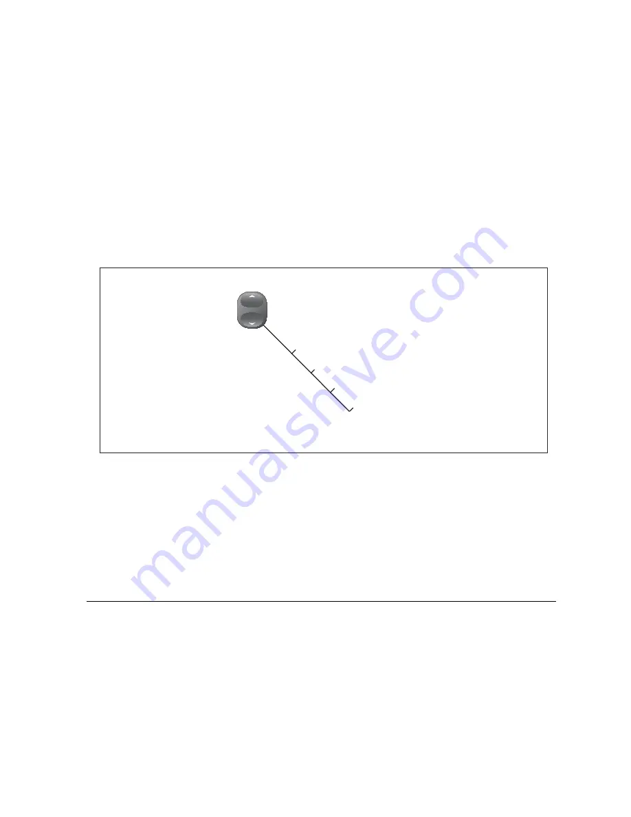
You can change the range for each displayed frequency from the Range Adjust toolbar, which gives you control over the range and range-
shift settings.

The DSM automatically adjusts the display to show the shallowest 
required range. Alternatively, you can range in or out on the image, 
up to the maximum depth displayed on the scrolling bottom and 
A-Scope images. Changes to the range affect all fishfinder 
windows.

To open the Range Adjust toolbar

1.  Press the 

RANGE

 button on the G-Series keyboard.

To select manual or auto range mode

1. Open the 

Range Adjust

 toolbar.

2. Toggle to 

AUTO

 or 

MAN

 on the RANGE softkey.

3. Press 

OK

.

Range shift

The DSM automatically adjusts the display to keep the bottom in 
the lower half of the display window. Alternatively, you can shift the 
image within the current range. Changes to the range shift are 
reflected in all Fishfinder windows.

To shift the range image

1. Open the 

Range Adjust

 toolbar.

2. Press the

 RANGE SHIFT

 softkey.

3. Select your desired setting using the rotary controller or 

trackpad.

4. Press 

OK

.

Range

auto/manual

Range shift

Select frequency 

high/low

High frequency shift

RANGE

OUT

IN

D10563-1

Summary of Contents for GPM400

Page 1: ...G Series Systems Reference Guide...

Page 2: ......

Page 3: ...G Series System Reference Guide Document Number 81276 1 Date June 2007...

Page 4: ...tered in all major marketing territories AST Autoadapt Auto GST Autoseastate Autotrim Bidata Marine Intelligence Maxiview On Board Raychart Raynav Raypilot Raystar ST40 ST60 Seaclutter Smart Route Tri...

Page 5: ...waypoints 39 4 8 Sorting the waypoint list 41 4 9 Waypoint groups 41 Chapter 5 The Chart Application 43 5 1 Warnings and cautions 44 5 2 Supplied cartography 44 5 4 Chart setup 46 5 8 Heading and cour...

Page 6: ...etup 128 11 3 Radar range and image quality 131 11 5 Using waypoints with the radar 135 11 9 Radar range 144 11 10 Measuring distance range and bearing 145 Chapter 12 Automatic Identification System 1...

Page 7: ...er 19 CompactFlash Cards and Managing Data 197 19 1 Cautions 198 19 2 Card insertion and removal 198 19 3 Saving and retrieving data 199 19 4 Sending and receiving data from a personal computer 199 19...

Page 8: ...G Series Installation Commissioning 8...

Page 9: ...This equipment must be installed in accordance with the instructions in the G Series System Installation Guide Failure to do so could result in poor product performance personal injury and or damage...

Page 10: ...associated with this device and accordingly release Raymarine Sirius Satellite Radio Inc and WSI Corporation from any and all claims arising from the use of this service By using this service you ackn...

Page 11: ...manufacture conforms to the appropriate Electro magnetic Compatibility EMC standards but correct installation is required to ensure that performance is not compromised Multi media chart cards The G S...

Page 12: ...G Series Reference Manual 12...

Page 13: ...omponents and features Chapter contents 1 1 Hardware overview on page 14 1 2 Display and keyboard on page 15 1 3 Installing and commissioning on page 17 1 4 System applications on page 17 See also Ope...

Page 14: ...3 DEF 1 CANCEL STANDBY DODGE PILOT OK RANGE OUT IN ENTER ENTER CANCEL MENU ENTER CANCEL MENU ENTER CANCEL MENU ENTER CANCEL MENU Navstation 1 Keyboard Monitor 1 Monitor 2 repeater SeaTalk Alarm sound...

Page 15: ...Nav Stations on your vessel Power button Controls system power For further information see Controlling system power on page 32 Rotary controller Choose items in menus or lists Turning the controller...

Page 16: ...d to configure page sets WPTS MOB Place waypoints WPTS or a Man Overboard Marker MOB and access waypoint functions Menu Open menus for changing system or application wide settings Active In multi wind...

Page 17: ...missioning This book assumes that a G Series system has already been cor rectly installed and commissioned on your vessel If you are about to install or commission a G Series system see the following...

Page 18: ...you are going Go to an existing waypoint Navigate a route Synchronize with the 2D chart Identify fishing spots D9521 2 See where the fish are Identify underwater objects View seabed structure View se...

Page 19: ...vessel on a rolling road in 3D perspective Give details of any correction required to steer your vessel along a given course View data about the distance and time to go until you reach a specified poi...

Page 20: ...G Series Reference Manual 20...

Page 21: ...the various buttons softkeys menus and toolbars The operating principles described in this section apply to all applications Understanding them will help you use the system efficiently Chapter conten...

Page 22: ...monitor you want to control from the keyboard When a keyboard is associated with a monitor this provides full control of the system For more information about using keyboards with monitors and Nav St...

Page 23: ...s not included Setup menus Menus are where you make system or application wide changes Pressing the MENU button opens the Setup menu From there you can choose application setup menus or system setup m...

Page 24: ...case but the system is not case sensitive it considers WAYPOINT 1 to be the same as Waypoint 1 To use special or accented characters turn on the Extended Char acter Set in the System Setup Menu see pa...

Page 25: ...ferent application views easily Choosing page sets Page set configurations apply to the monitor on which you are working You can display different pages on other monitors in your Nav Station To select...

Page 26: ...r toggle between the applications configured in the page set by pressing PAGE 3 Press OK or CANCEL Selecting application windows When the selected page has more than one window the window that is curr...

Page 27: ...rocker switch to change the scale of the view When you zoom in you see a smaller area of the chart in more detail large scale When you zoom out you see a greater area of the chart in less detail small...

Page 28: ...tomisable content Vertical or horizontal format Display or hide Normal or large size Data base lists Contain information you have added to the display s memory e g waypoints Highlight an entry using t...

Page 29: ...on the SeaTalk system Placing a MOB marker initiates a set of actions on the G Series system Waypoint placed at your current position Alarm sounds in morse repeated every 30 seconds Positional inform...

Page 30: ...e your settings Cancelling alarms There are two kinds of alarm system and external System alarms are triggered by G Series applications like the chart or radar When you cancel a system alarm the G Ser...

Page 31: ...power on and system setup procedures Chapter contents 3 1 Controlling system power on page 32 3 2 Monitor settings on page 32 3 3 Keyboard settings on page 33 3 4 Setting language date and time and u...

Page 32: ...r systems Brightness and power settings for the monitors Monitor palette selection 3 2 Monitor settings If you are using a Raymarine monitor the power control screen allows you to set the monitor brig...

Page 33: ...ll these settings are configured from the system Setup menu To configure language units date and time format 1 Open the system Setup Menu 2 Select the settings you want to configure 3 Make the appropr...

Page 34: ...G Series Reference Manual 34...

Page 35: ...Chapter contents 4 1 Introducing waypoints on page 36 4 2 The waypoint toolbar on page 37 4 3 Waypoint list on page 38 4 4 Placing waypoints on page 38 4 5 Navigating to waypoints on page 39 4 6 Waypo...

Page 36: ...on window is active but it will not be seen in the weather window Radar and 2D chart windows A waypoint is represented on a radar or chart window when it is inactive or active i e you are navigating t...

Page 37: ...NT AT CURSOR WAYPOINT AT VESSEL WAYPOINT AT LAT LON GOTO WAYPOINT OPTIONS REVIEW AND EDIT WAYPOINTS Set up default symbol group Edit default Sort list Set default symbol and group Waypoint groups View...

Page 38: ...lash card or transfer them to other NMEA compatible instruments If the G Series system receives an active waypoint over SeaTalk or NMEA it is displayed but cannot be edited Waypoint lists can be passw...

Page 39: ...2 Press the GOTO WAYPOINT softkey or 1 Press either the WPTS MOB button or GOTO softkey 2 Press the GOTO WAYPOINT OPTIONS softkey 3 Select the appropriate waypoint from the list 4 Press GOTO WAYPOINT...

Page 40: ...ls to mark different types of position fish or dive locations for example When a waypoint is active being navigated to the system highlights it by placing a red box around it Alternative waypoint symb...

Page 41: ...ypoint from the list 4 Press the ERASE WAYPOINT softkey 5 Confirm the deletion To erase all waypoints 1 Press the DATA button 2 Press the ARCHIVE AND TRANSFER softkey 3 Press the ERASE FROM SYSTEM sof...

Page 42: ...o 5 Highlight the waypoint you want to move 6 Press MOVE WAYPOINT FROM A TO B 7 Press OK when done To rename a group 1 Open the waypoint group list 2 Highlight the group you want to rename 3 Press the...

Page 43: ...arnings and cautions on page 44 5 2 Supplied cartography on page 44 5 3 Chart Overview on page 45 5 4 Chart setup on page 46 Navigation 5 5 Quick waypoints on page 50 5 6 Building a route on page 52 5...

Page 44: ...e receiving position and heading data from your vessel s Global Positioning System GPS 2 For your GPS and chart to correlate accurately with your paper charts they all need to use the same datum The d...

Page 45: ...y tells you which orientation and motion mode you are in For more details see page 66 If your position is outside the area of chart currently shown in the chart window the vessel symbol will not be vi...

Page 46: ...atum option on the Chart Setup menu FUNCTION OPTIONS Object Information OFF No info pop up is displayed but detailed data can still be displayed by pressing OK All ON Displays an information pop up fo...

Page 47: ...rt Offset in the Chart Setup Menu 2 Toggle OFFSET to ON 3 Press the SET OFFSET softkey 4 Adjust the North South and East West offset values by pressing the corresponding softkey and using either the t...

Page 48: ...ay be triggered in the chart application System anchor timer alarm clock and temperature Navigation arrival and off track Radar guard zones Fishfinder AIS Weather Nav Marks ON OFF Nav Marks Symbols Th...

Page 49: ...some cases appropriate action is taken automatically by the G Series system For example following an arrival alarm the next route leg is activated To configure alarms 1 Press the MENU button to open t...

Page 50: ...o from the default chart toolbar using the GOTO softkey This lets you set a temporary way point at the cursor position and track to it When you reach the waypoint it is erased The waypoint you set is...

Page 51: ...within the waypoint list To use the cursor to select a waypoint 1 Move the cursor over the waypoint 2 Press GOTO WAYPOINT To select a waypoint from the waypoint list 1 On the Chart application toolbar...

Page 52: ...Follow route options Build new route TRACKS PRESENTATION Show hide routes Review and edit routes Sort waypoint list Insert waypoint Use cursor Make route Place waypoint Follow from here Move waypoint...

Page 53: ...nt to re use in a new route The way in which the OK and CANCEL buttons operate is dif ferent when you are building and editing routes see below Building a route in chart view The chart view lets you b...

Page 54: ...ghlight the waypoint you want to remove from a route 2 Press REMOVE WAYPOINT To abandon the route build completely 1 In chart view or in waypoint list view press CANCEL 2 Confirm by pressing YES Savin...

Page 55: ...ress the FOLLOW THIS ROUTE or FOLLOW FROM HERE softkey To select a route to follow in the routes list 1 Press either the GOTO or ROUTES softkey 2 Press the FOLLOW ROUTE OPTIONS softkey 3 On the Route...

Page 56: ...aypoint and then the system automatically activates the reverse follow route function Advance waypoints You can tell the system to ignore the next waypoint in your route and advance directly to the wa...

Page 57: ...anges to it if necessary FIND GOTO ROUTES Follow route options Build new route TRACKS PRESENTATION Show hide routes Review and edit routes Route list Place waypoint Erase route Amend route course Rout...

Page 58: ...he added waypoint 4 In the left hand column highlight the waypoint you want to add to the list 5 Press the INSERT WAYPOINT softkey 6 Press the SAVE ROUTE softkey To create and add a new waypoint 1 Hig...

Page 59: ...ase a route 1 Select the route you want to delete 2 Press the ERASE ROUTE softkey You can also erase all or selected routes using the ARCHIVE TRANSFER function Timed routes Details of all the routes y...

Page 60: ...reate the track You can save the track to review your journey at a later date or to retrace it You can convert a track to a route enabling its use with the navigation options of the chart application...

Page 61: ...ou can use it in the same way as all your other routes Note If the power fails while a track is being recorded or if the position fix is lost a break will occur in the track Only the last contiguous s...

Page 62: ...have specified 3 mins 6 mins or infinite in the Chart Setup Menu see page 46 at the current speed Any times that you specify apply to all chart views and if INFINITE is selected the vector will exten...

Page 63: ...shown below FIND GOTO ROUTES Chart view local system Declutter on off Chart layers Chart mode and orientation TRACKS PRESENTATION Show hide waypoints Show waypoints Show by sym group Aerial overlay R...

Page 64: ...art layers You can overlay data onto a chart window to give greater depth of information You can overlay radar AIS or range rings Radar overlay Overlaying the chart image with radar data allows for be...

Page 65: ...g and risk analysis Although set up in radar mode or radar overlay all MARPA targets are displayed in the chart win dow from which you can also access MARPA functions For detailed information about MA...

Page 66: ...ntation on screen and choose your preferred chart orientation Find This is a shortcut softkey that has the same effect as the FIND key on the default toolbar It centers the chart display on either the...

Page 67: ...in the status bar by putting the motion name in parentheses Manually changing the range in autorange also suspends motion mode When a chart window is set to SYSTEM view the motion mode will be set bu...

Page 68: ...hide routes and tracks 1 Highlight a route or track and press the HIDE softkey or 1 Open the Route or Track list 2 Highlight a route or track in the list 3 Toggle between SHOW and HIDE settings with...

Page 69: ...databar displays FISH to indicate that you are in that mode but without data Displaying details for objects and features Many objects shown on the chart have detailed information associ ated with them...

Page 70: ...the movement of currents and tides for times you specify You can set the date for the animation and choose to see the whole animation from the beginning or start it at any point within a 24 hour perio...

Page 71: ...ces by using the FIND NEAR EST function Alternatively you can use either of the methods below To display port services 1 Highlight a port symbol 2 Press OK 3 Highlight a service 4 Press the VIEW DETAI...

Page 72: ...ces and points of interest are indicated by the following symbols Highlighting any of the above service symbols gives you the follow ing information about the business Name Address Telephone number Ty...

Page 73: ...dark blue and light blue respectively and to view land features simultaneously To specify the overlay area 1 Open the Cartography Setup Menu 2 Select Aerial Photo Overlay 3 Choose your preferred setti...

Page 74: ...G Series Reference Manual 74 To clear the ruler 1 Press DATA 2 Press the RULER softkey 3 Press CLEAR RULER...

Page 75: ...Chapter contents 6 1 Safety notice on page 76 6 2 3D chart requirements on page 76 6 3 Setting up the 3D chart on page 76 6 4 The 3D chart view on page 76 6 5 Operation modes on page 77 6 6 Using the...

Page 76: ...uires heading and position data 6 3 Setting up the 3D chart The 3D chart setup menu is available from the system setup menu For information on using the system setup menu see To change a menu setting...

Page 77: ...iew away from your current location the system enters planning mode You can view areas from different angles bearings and ranges but your vessel is no longer kept on screen automatically The same cont...

Page 78: ...t view The default toolbar includes two softkeys dedicated to adjusting the view of the 3D chart application ADJUST lets you rotate the view and adjust the angle pitch ADJUST ON sets the reference poi...

Page 79: ...enable adjustment To set the adjustment reference point 1 Press the ADJUST ON softkey 2 Toggle to EYE or CENTER as required 3 Press OK Navigation options Shortcuts to the Route List and Waypoint List...

Page 80: ...rs shown below Chart layers 3D view options View to forward starboard aft port Trans cone on off Depth scale on off Adjust exaggeration Waypoint name on off Depth overlay on off Depth plane value Wayp...

Page 81: ...a different angle Up to four different areas of the chart For information about setting up application windows see Selecting application windows on page 26 6 8 Tuning the view You can tune the 3D char...

Page 82: ...ftkey 3 Press ADJUST EXAGGERATION 4 Use the rotary controller to set your level of exaggeration 5 Press OK Press CANCEL at any time to return to the previous exaggeration setting Declutter In some cir...

Page 83: ...D view locator The view locator is a polygon displayed on the standard chart which outlines the boundaries of the area shown on the 3D chart It is shown as a blue line extending from the virtual eye p...

Page 84: ...onize the 2D chart with the 3D chart or the radar but not both To synchronize the standard chart with the 3D chart 1 Make a 2D chart window active 2 Press the PRESENTATION softkey 3 Press CHART MODE A...

Page 85: ...nctions do not replace the autopilot control head You must have a pilot control head installed before you enable or engage the autopilot Chapter contents 7 1 Emergency disengage on page 86 7 2 Enablin...

Page 86: ...ontrol screen 1 Press the PILOT button If you press OK or CANCEL without engaging the autopilot you go back to the navigation screen with the autopilot disengaged When the autopilot is engaged or you...

Page 87: ...the ENGAGE PILOT TRACK softkey to engage the autopi lot and continue to the next waypoint in your route Press the CLEAR ALARM softkey to silence the alarm and keep the autopilot engaged in auto mode...

Page 88: ...Waypoint field The toolbar gives you three options Press CLEAR ALARM to silence the alarm and keep the autopilot engaged in auto mode continuing on the current heading Press STANDBY to silence the ala...

Page 89: ...89 Chapter 7 Autopilot Integration...

Page 90: ...G Series Reference Manual 90...

Page 91: ...der on page 92 8 4 Explaining the readout on page 93 8 5 Factors influencing the readout on page 93 8 6 Display mode settings on page 95 8 7 Presentation toolbar on page 101 8 8 Adjusting gain and pow...

Page 92: ...t colors You can use this information to determine the shape and make up of the seabed or the size of shoals or of other objects 8 3 Operating the fishfinder The fishfinder provides you with four pres...

Page 93: ...the fishfinder display Depth As sea depth increases signal strength decreases resulting in a lighter on screen image of the bottom Object size The larger an object is the stronger its return on the fi...

Page 94: ...us frequencies may be available on your system depending on the transducers fitted to your vessel Viewing single or dual frequencies If the preset you are using includes two frequencies you can use on...

Page 95: ...display mode settings to suit your requirements Changes to the display mode are saved with the preset at power off Adjust F1 F2 Select option Zoom full split Full split 1 2 3 Range rotary Bottom shif...

Page 96: ...to a different point in the display When the range increases the area shown in the zoom window also increases Full or split screen You can either replace the standard fishfinder image with the zoomed...

Page 97: ...the bottom lock image allows you to view more bottom details You can also reposition the image on screen to anywhere between the bottom of the window 0 and the mid dle of the window 50 by using the Bo...

Page 98: ...CT OPTION softkey 2 Choose your mode on the A SCOPE MODE softkey D6674 3 MODE 1 The A scope image is centred in the window MODE 2 The left hand side of the Mode 1 image is expanded to give a more deta...

Page 99: ...1 Press the RANGE button on the G Series keyboard To select manual or auto range mode 1 Open the Range Adjust toolbar 2 Toggle to AUTO or MAN on the RANGE softkey 3 Press OK Range shift The DSM autom...

Page 100: ...G Series Reference Manual 100 To return to the standard fishfinder image 1 Toggle to AUTO on the RANGE softkey 2 Press OK...

Page 101: ...a scroll control These settings affect the monitor you are working on ADJUST P1 SINGLE PRESET 2 DUAL PRESET 3 SHALLOW PRESET 4 DEEP Gain Power Auto Man PRESENTATION VRM View F1 F2 Both Scroll pause re...

Page 102: ...y set gain levels If necessary you can set gain levels manually Manually set gain levels are applied to the active window and any other fishfinder win dows displaying that frequency To set the gain le...

Page 103: ...pth The size and position of this readout can be changed in the Fishfinder display Setup menu see page 107 Depth lines horizontal dashed lines drawn at regular intervals to indicate the depth from the...

Page 104: ...are look ing for fish If you select a slower speed the information remains on the display for longer The following options are available Manual This allows you to set the scroll speed as a percent ag...

Page 105: ...er than the deep limit You can switch the alarms on set the limits and specify the fish alarm sensitivity 8 11 Editing presets You can select frequencies for each preset from the Setup Fre quency Pres...

Page 106: ...t selection NONE MAN Manual setting is fixed AUTO Automatically selects highest frequency and widest beam AUTO Automatically adjusts to suit depth DSM300 AUTO Changes with depth alter nate pings of 50...

Page 107: ...to use setup menus see Setup menus on page 23 To open the fishfinder setup menu 1 Make a fishfinder window active 2 Press the MENU button 3 Select Fishfinder Setup Fishfinder Setup Configure Preset F...

Page 108: ...tration Color Palette Choose the color palette to suit your conditions or personal preference 75 9ft 100 75 200 kHz Auto Gain Auto High 75 9ft 100 75 200 kHz Auto Gain Auto High 75 9ft 200 kHz Auto Ga...

Page 109: ...rline Offset represents the depth of the transducer relative to the waterline Speed and temperature offsets Calibrate the speed transducer and thermistor if fitted DSM Reset Restores all settings to f...

Page 110: ...G Series Reference Manual 110...

Page 111: ...and advisories refer to the NOAA website at www nws noaa gov Chapter contents 9 1 Disclaimer on page 112 9 2 Weather application pre requisites on page 112 9 3 Weather application setup on page 112 9...

Reviews: