40
E-Series Installation Manual
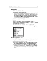
Radar alignment checks
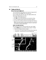
You should check the bearing and display timing alignment to ensure that an accurate
picture is shown.
Adjusting the bearing alignment ensures that targets appear at the correct bearing
relative to your boat’s bow. You need to select a visible target of known bearing that is
displayed on the radar, and then adjust the radar set up as necessary until the correct
bearing reading is obtained. You can carry out a bearing alignment in two ways:
Bearing alignment with your boat moored
To use this method you will need a hand bearing compass:
1. Visually identify a suitable target, such as a buoy that can be seen towards the edge
of the radar screen. Typically, this will be on the 1.5nm range.
2. Determine the accurate bearing of the target relative to your boat’s bow using the
hand bearing compass. To do this subtract your boat head bearing from the target
visual bearing, these examples may help:
3. From the primary radar soft keys, press VRM/EBL.
4. Toggle the VRM/EBL soft key to ON. Adjust the EBL to your chosen target. If there is
a difference between your calculated bearing and that shown for the EBL, there is
an alignment error and you will need to carry out bearing alignment adjustment
(see below).
Bearing alignment with your boat under way
1. Align your boat’s bow with the selected target.
2. Note the position of the target relative to the Ships Heading Marker (SHM) on the
radar picture. If the target is not under the SHM, there is an alignment error and you
will need to carry out bearing alignment adjustment. For details see below
.
Adjusting the bearing alignment
1. If moored, move the EBL to calculate bearing.
2. With a radar application in the active window, press MENU. The Set Up menu is dis-
played.
Example 1
Example 2
Visual bearing (a) = 065° M
Visual bearing (a) = 030° M
Ships head bearing (b) = 021° M
Ships head bearing (b) = 042° M
Relative bearing:
= (a) - (b)
= 065 - 021 = 044° R
Relative bearing:
= (a) - (b)
= 030 - 042 = -012
If answer is negative, add 360° =
-012 + 360 = 348° R
Summary of Contents for E120W
Page 1: ...E Series Networked Display Installation Manual Document Number 87043_2 Date March 2006...
Page 6: ...iv E Series Networked Display Installation Manual...
Page 14: ...8 E Series Installation Manual...
Page 26: ...20 E Series Installation Manual...


