Chapter 1: Preparation for installation
7
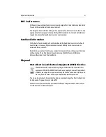
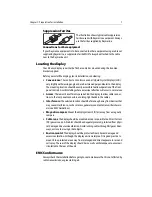
Suppression Ferrites
The illustration shows typical cable suppression
ferrites used with Raymarine equipment. Always
use the ferrites supplied by Raymarine.
Connections to other equipment
If your Raymarine equipment is to be connected to other equipment using a cable not
supplied by Raymarine, a suppression ferrite MUST always be attached to the cable
near to the Raymarine unit.
Locating the display
Your E-Series display can either be flush-mounted or mounted using the trunnion
bracket supplied.
Before you install the display, plan its installation, considering:
•
Convenience
: The contrast and colors seen on all Liquid Crystal Displays (LCD)
vary slightly with viewing angle and are best viewed perpendicular to the display.
The mounting location should be easily accessible to allow operation of the front
panel controls. Avoid installing where excessive reflection will occur in normal use.
•
Access
: There must be sufficient space behind the display to allow cable connec-
tions to the rear panel connectors, avoiding tight bends in the cables.
•
Interference
: The selected location should be far enough away from devices that
may cause interference, such as motors, generators and radio transmitters/receiv-
ers (see EMC Guidelines).
•
Magnetic compass
: Mount the display at least 3ft (1m) away from a magnetic
compass.
•
Cable runs
: The display should be mounted as near as possible to a Direct Current
(DC) power source. All cables should be adequately secured, protected from physi-
cal damage and excessive vibration. Avoid running cables through bilges or door-
ways, or close to moving or hot objects.
•
Environmental
: The display should be protected from physical damage and
excessive vibration. Although the display unit is waterproof, it is good practice to
mount it in a protected area away from prolonged and direct exposure to rain and
salt spray. The rear of the display should be in a well ventilated space to ensure air
circulation to the rear of the unit.
EMC Conformance
Always check the installation before going to sea to make sure that it is not affected by
radio transmissions, engine starting etc.
D6626-1
Summary of Contents for E120W
Page 1: ...E Series Networked Display Installation Manual Document Number 87043_2 Date March 2006...
Page 6: ...iv E Series Networked Display Installation Manual...
Page 14: ...8 E Series Installation Manual...
Page 26: ...20 E Series Installation Manual...


