28
E-Series Installation Manual
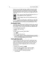
2. Using a pair of pliers, crimp the connector bulb together.
3. Check that a secure connection has been made.
4. Ensure that the cables are secured in a suitable position to prevent the join being
placed under strain.
Cable types
This sections details the various cables used by your display. Please read these
guidelines carefully and ensure that you follow the recommendations given.
Power cable (R89005)
The E-Series Display is intended for use on boats’ DC power systems
rated at 12v or 24v.
The power connection should be made at either the output of the
battery isolating switch, or at a DC power distribution panel. Raymarine
recommends that power is fed directly to the display and scanner via its
own dedicated cable system and MUST be protected by a thermal circuit
breaker or fuse, installed close to the power connection.
Do not fit switches or circuit breakers in such a way that power may be
removed from part of the E-Series networked system while leaving the
rest of the system running, as this may result in unit malfunction.
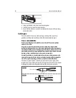
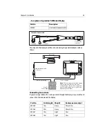
This cable is supplied ready for connecting to your boats DC power supply, with a
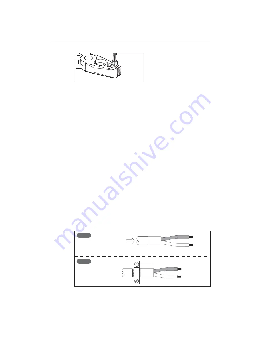
length of screen exposed before the positive and negative wire tails.This screen should
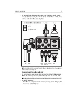
be clamped to your boat’s earth/ground with a saddle clamp, as shown below:
cable splicer
D6615_3
Slide towards tails
Pre-cut line
Attach to ship's ground
Step 1
Step 2
D6621-2
Summary of Contents for E120W
Page 1: ...E Series Networked Display Installation Manual Document Number 87043_2 Date March 2006...
Page 6: ...iv E Series Networked Display Installation Manual...
Page 14: ...8 E Series Installation Manual...
Page 26: ...20 E Series Installation Manual...


