background image

6.3 GNSS troubleshooting

Problems with the GNSS and their possible causes and solutions are described here.
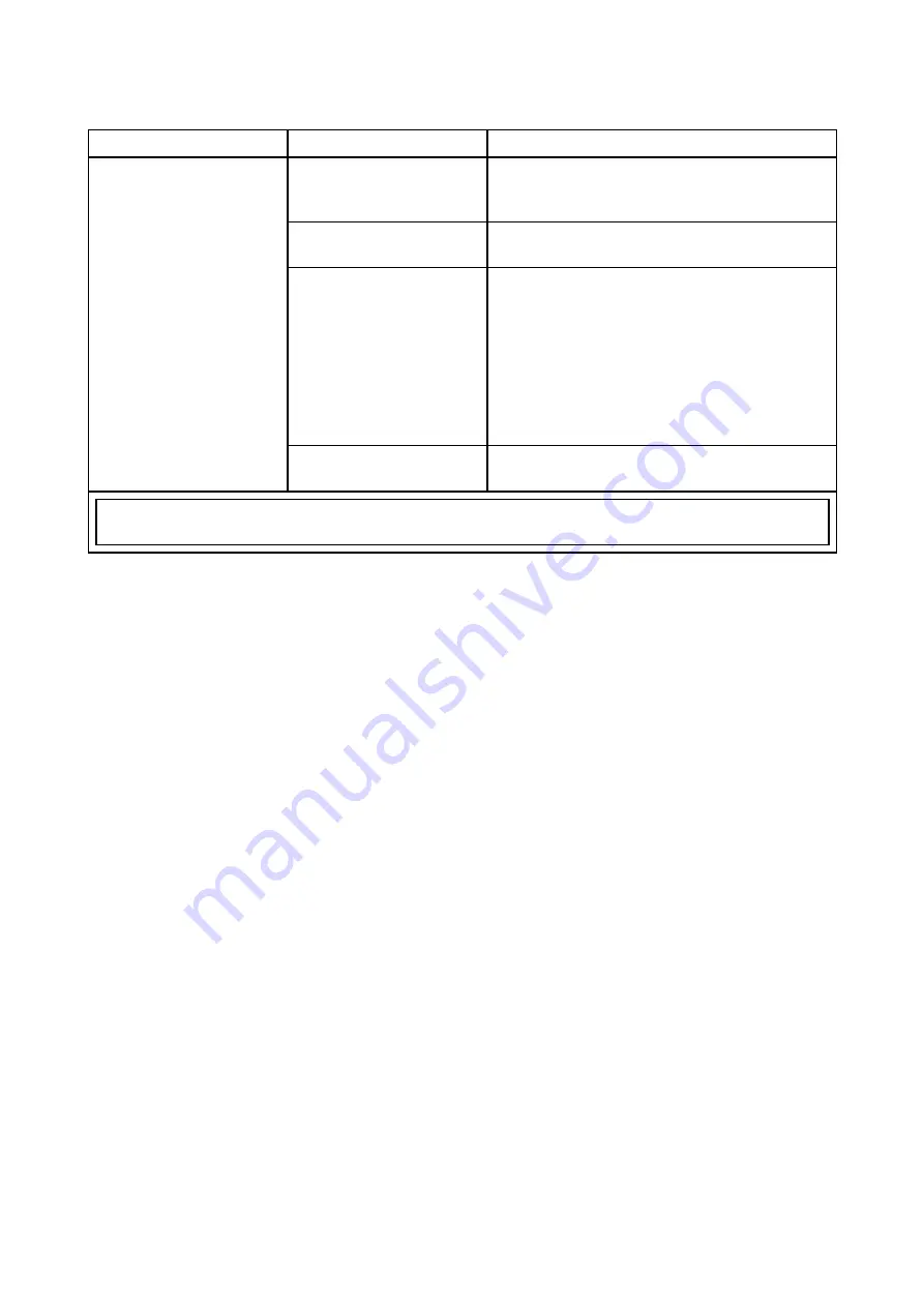
Problem

Possible causes

Possible solutions

Geographic location or
prevailing conditions
preventing satellite fix.

Check periodically to see if a fix is obtained
in better conditions or another geographic
location.

GNSS connection fault.

Ensure that external GNSS connections and
cabling are correct and fault free.

External GNSS receiver
in poor location.
For example:

• Below decks.

• Close proximity

to transmitting
equipment such as
VHF radio.

Ensure GNSS receiver has a clear view of
the sky.

“No Fix” GNSS status
icon is displayed.

GNSS installation
problem.

Refer to the installation instructions.

Note:

A GNSS Status screen is accessible from the display. This provides satellite signal strength

and other relevant information.

58

Summary of Contents for Axiom Pro 12

Page 1: ... 2017 Raymarine UK Limited 87319 2 Document number 10 2017 Date English en US Installation instructions ...

Page 2: ......

Page 3: ...nts design patents patents pending or design patents pending Fair Use Statement You may print no more than three copies of this manual for your own use You may not make any further copies or distribute or use the manual in any other way including without limitation exploiting the manual commercially or giving or selling copies to third parties Software updates Check the Raymarine website for the l...

Page 4: ......

Page 5: ...n Displays 15 2 3 Compatible transducers Axiom Pro MFDs 16 RealVision transducers 16 DownVision transducers 17 CHIRP conical beam transducers using DownVision type connector 17 2 4 Parts supplied Axiom Pro 9 and 12 19 2 5 Parts supplied Axiom Pro 16 20 Chapter 3 Installation 21 3 1 Selecting a location 22 General location requirements 22 EMC installation guidelines 22 RF interference 23 Compass sa...

Page 6: ...5 1 Service and maintenance 52 Routine equipment checks 52 5 2 Product cleaning 53 Cleaning the display case 53 Cleaning the display screen 53 Cleaning the sun cover 53 Chapter 6 Troubleshooting 55 6 1 Troubleshooting 56 6 2 Power up troubleshooting 57 Performing a Power on Reset 57 6 3 GNSS troubleshooting 58 6 4 Sonar troubleshooting 59 6 5 Wi Fi troubleshooting 62 6 6 Touchscreen troubleshootin...

Page 7: ...n 75 Chapter 9 Spares and accessories 77 9 1 AXIOM Pro accessories 78 Axiom transducer adaptor cables 78 Legacy MFD adaptor plates 78 9 2 AXIOM Pro spares 79 9 3 RayNet to RayNet cables and connectors 80 RayNet to RJ45 adapter cables 81 9 4 SeaTalk ng cables and accessories 83 7 ...

Page 8: ...8 ...

Page 9: ...or by errors in chart data or information utilized by the product and supplied by third parties This product supports electronic charts provided by third party suppliers which may be embedded or stored on memory card Use of such charts is subject to the supplier s End User Licence Agreement RF exposure This equipment complies with FCC IC RF exposure limits for general population uncontrolled expos...

Page 10: ...equency band used for this device campus radio stations radios stations that require a license and specified low power radio stations radio stations that do not require license for mobile identification and amateur radio stations radio stations that require license used in industries such as microwave ovens scientific medical equipment devices and production line of other factories are also being ...

Page 11: ...u will need this serial number when registering your product online You should retain the label for future reference Technical accuracy To the best of our knowledge the information in this document was correct at the time it was produced However Raymarine cannot accept liability for any inaccuracies or omissions it may contain In addition our policy of continuous product improvement may change spe...

Page 12: ...12 ...

Page 13: ...ents 2 1 Product documentation on page 14 2 2 Applicable products on page 15 2 3 Compatible transducers Axiom Pro MFDs on page 16 2 4 Parts supplied Axiom Pro 9 and 12 on page 19 2 5 Parts supplied Axiom Pro 16 on page 20 Document and product information 13 ...

Page 14: ...marine product Visit http www raymarine co uk view id 5175 to order a printed manual delivered directly to your door For further information about the Print Shop please visit the Print Shop FAQ pages http www raymarine co uk view id 5751 Note Accepted methods of payment for printed manuals are credit cards and PayPal Printed manuals can be shipped worldwide Further manuals will be added to the Pri...

Page 15: ...D and 1kW sonar module E70481 Axiom Pro 9 S 9 MFD with built in 600W sonar module E70372 Axiom Pro 12 RVX 12 MFD with built in RealVision 3D and 1kW sonar module E70482 Axiom Pro 12 S 12 MFD with built in 600W sonar module E70373 Axiom Pro 16 RVX 16 MFD with built in RealVision 3D and 1kW sonar module E70483 Axiom Pro 16 S 16 MFD with built in 600W sonar module Document and product information 15 ...

Page 16: ... the Raymarine website for compatible transducers www raymarine com transducers Other transducers using available adaptor cables RealVision transducers The transducers listed below can be connected directly to RealVision 3D variant MFDs Product number Transducer Mounting Description A80464 Transom RV 100 RealVision 3D Plastic Transducer A80465 Thru Hull RV 200 RealVision 3D Bronze 0 Single Transdu...

Page 17: ...The transducers listed below can be connected directly to DownVision DV variant MFDs or via an adaptor cable to RealVision RV RealVision 1kW RVX and Sonar S variant MFDs CPT S transducers use CHIRP sonar technology to produce a conical shaped sonar beam Note CPT S transducers do NOT offer DownVision capabilities Product number Transducer Mounting Description E70342 Transom CPT S plastic E70339 Thr...

Page 18: ...Product number Transducer Mounting Description E70340 Thru hull CPT S 12 angled element bronze E70341 Thru hull CPT S 20 angled element bronze 18 ...

Page 19: ...t gasket 4 Suncover 5 Trunnion bracket 6 Trunnion knobs x 2 7 Fixings M4 x 40 pan head bolt x 4 M4 Nylock nut x 4 and M4 washer x 4 8 M3x5 screw M3 spring washer and M3 crimp terminal for optional grounding connection 9 Power Video NMEA 0183 cable 1 5 m 4 92 ft straight 10 Documentation pack 11 RayNet 2 m 6 6 ft network cable 12 SeaTalkng to DeviceNet adaptor cable Document and product information...

Page 20: ...d Upper keypad 3 Panel mount gasket 4 Suncover 5 Documentation pack 6 SeaTalkng to DeviceNet adaptor cable 7 Fixings M4 x 40 pan head bolt x 4 M4 Nylock nut x 4 and M4 washer x 4 8 Power Video NMEA 0183 cable 1 5 m 4 92 ft straight 9 M3x5 screw M3 spring washer and M3 crimp terminal for optional grounding connection 10 RayNet 2 m 6 6 ft network cable 20 ...

Page 21: ...Chapter 3 Installation Chapter contents 3 1 Selecting a location on page 22 3 2 Mounting options on page 28 3 3 Surface mounting on page 29 3 4 Bracket trunnion mounting on page 31 Installation 21 ...

Page 22: ...equipment Any specific requirements for each system component are provided later in this chapter Mounting surface Ensure product is adequately supported on a secure surface Do not mount units or cut holes in places which may damage the structure of the vessel Cabling Ensure the product is mounted in a location which allows proper routing support and connection of cables Minimum bend radius of 100 ...

Page 23: ...include LED spot or strip lights and terrestrial TV tuners To minimize interference from such equipment Keep it as far away from GPS AIS or VHF devices as possible Ensure that any power cables for external equipment are not entangled with the power or data cables for GPS AIS or VHF devices Consider fitting one or more high frequency suppression ferrites to the EMI emitting device The ferrite s sho...

Page 24: ...s can also have an impact In particular steel aluminium or carbon surfaces can impact GPS performance Before locating equipment with an internal GPS antenna below decks or on a steel aluminium or carbon construction vessel or surface seek professional assistance Prevailing conditions The weather and location of the vessel can affect the GPS performance Typically calm clear conditions provide for a...

Page 25: ...products Distance and signal strength The distance between Wi Fi products should always be kept to a minimum Do not exceed the maximum stated range of your Wi Fi product Maximum range will vary for each device Wi Fi performance degrades over distance so products farther away will receive less network bandwidth Products installed close to their maximum Wi Fi range may experience slow connection spe...

Page 26: ...Pro 12 A 299 32 mm 11 78 in 358 03 mm 14 1 in B 329 5 mm 12 97 in 388 5 mm 15 3 in C 186 2 mm 7 33 in 246 13 mm 9 69 in D 173 79 mm 6 84 in 222 8 mm 8 77 in E 33 4 mm 1 31 in 31 9 mm 1 26 in F 64 5 mm 2 54 in 64 4 mm 2 54 in G 137 05 mm 5 4 in straight connector 117 05 mm 4 61 in right angled connector 137 1 mm 5 4 in straight connector 117 1 mm 4 61 in right angled connector H 12 86 mm 0 51 in 12...

Page 27: ... in B 258 mm 10 16 in C 33 4 mm 1 31 in D 68 4 mm 2 69 in E 138 6 mm 5 46 in straight connector 118 6 mm 4 67 in right angled connector F 15 2 mm 0 6 in G 207 mm 8 15 in straight connector 187 mm 7 36 in right angled connector Installation 27 ...

Page 28: ...ed The Axiom Pro 9 and 12 can also be bracket mounted on a trunnion Legacy MFD adaptor plates are also available to enable you to easily swap out older MFDs for new Axiom Pro MFDs please refer to Chapter 9 Spares and accessories for a list of available adaptors 28 ...

Page 29: ...cut out line 5 Ensure that the unit fits into the removed area and then file around any rough edges until smooth 6 Drill 4 holes as indicated on the template to accept the fixings 7 Place the gasket onto the rear of the display and press firmly onto the flange 8 Connect the power data and other cables to the MFD 9 Slide the unit into place and secure using the fixings provided 10 Attach the Menu H...

Page 30: ...ed to remove the MFD once installed then the bezel pieces will need to be removed to gain access to the fixings 1 Carefully insert the tip of a small flat blade screw driver into the recessed areas around the edge of the bezel pieces 2 Gently lever the screw driver to push the bezel piece forward away from the display The bezel piece should now come away from the display easily 30 ...

Page 31: ...urced adequate fixings to secure the bracket to your mounting surface Attached the Menu Home buttons and bezel pieces 1 Using the Bracket as a template Mark and drill 5 x pilot holes on the mounting surface 2 Use self tapping screws to secure the trunnion bracket to the mounting surface If the mounting surface is too thin for the screws provided use stainless steel machine screws washers and locki...

Page 32: ...32 ...

Page 33: ...ction on page 37 4 3 NMEA 2000 SeaTalkng connection on page 42 4 4 NMEA 0183 connection on page 43 4 5 Transducer connection on page 44 4 6 Network connection on page 46 4 7 GA150 connection on page 47 4 8 Accessory connection on page 48 4 9 Analog video connection on page 49 Connections 33 ...

Page 34: ...enna GA150 s fitted cable NMEA 2000 connection SeaTalkng backbone NMEA 2000 backbone SeaTalkng to DeviceNet adaptor cable DeviceNet cables Network connection x 2 RayNet network or device RayNet cable with female connector Accessory connection RCR SDUSB remote card reader RCR 2 remote card reader RCR SDUSB RCR 2 s fitted cable 34 ...

Page 35: ... battery terminal Refer to Grounding optional dedicated drain wire section for details Depending on MFD variant different transducer connections are available Axiom Pro RVX transducer connection options Connector Connects to Suitable cables RealVision 3D transducers Transducer s fitted cable Extension cable Adaptor cable 1kW transducers Transducer s fitted cable Extension cable Adaptor cable Conne...

Page 36: ...roduct 1 Ensure that the vessel s power supply is switched off 2 Ensure that the device being connected has been installed in accordance with the installation instructions supplied with that device 3 Ensuring correct orientation push cable connectors fully onto the corresponding connectors 4 If applicable engage any locking mechanism to ensure a secure connection 5 Ensure any bare ended wire conne...

Page 37: ...in doubt consult an authorized Raymarine dealer Your product s power cable may have fitted in line fuse if not then you can add an in line fuse to the positive wire of your products power connection Caution Power supply protection When installing this product ensure the power source is adequately protected by means of a suitably rated fuse or automatic circuit breaker Power distribution Recommenda...

Page 38: ...ed power cable is NOT fitted with an inline fuse you MUST fit a suitably rated fuse or breaker between the red wire and the battery s positive terminal Refer to the inline fuse ratings provided in the product s documentation If you need to extend the length of the power cable supplied with your product ensure you observe the dedicated Power cable extensions advice provided in the product s documen...

Page 39: ...ce by 8 AWG 8 36 mm2 cable Ideally all equipment should be wired to individual suitably rated thermal breakers or fuses with appropriate circuit protection Where this is not possible and more than 1 item of equipment shares a breaker use individual in line fuses for each power circuit to provide the necessary protection 1 Positive bar 2 Negative bar 3 Circuit breaker 4 Fuse In all cases observe th...

Page 40: ...ge of 10 8 V at the product s power connector with a fully flat battery at 11 V Important Be aware that some products in your system such as sonar modules can create voltage peaks at certain times which may impact the voltage available to other products during the peaks Grounding Ensure that you observe the separate grounding advice provided in the product s documentation More information It is re...

Page 41: ... negative battery terminal The dc power system should be either Negative grounded with the negative battery terminal connected to the vessel s ground or Floating with neither battery terminal connected to the vessel s ground If several items require grounding they may first be connected to a single local point e g within a switch panel with this point connected via a single appropriately rated con...

Page 42: ...r cable to connect your MFD to a SeaTalkng backbone 2 Alternatively your can connect your MFD to a NMEA 2000 backbone using a standard DeviceNet cable not supplied Note 1 SeaTalkng and NMEA 2000 devices must be connected to a correctly terminated backbone that the MFD is also connected to Devices cannot be connected directly to the MFD 2 Refer to the instructions supplied with your SeaTalkng NMEA ...

Page 43: ... NMEA 0183 device connected to Port 1 INPUT and another NMEA 0183 device connected to Port 1 OUTPUT both NMEA devices must use the same baud rate Up to 4 devices can be connected to the display s output port and up to 2 devices to the display s input ports Item Device Cable color Port Input output Positive negative 1 White 1 Input Positive 2 Green 1 Input Negative 3 Yellow 1 Output Positive 4 Brow...

Page 44: ...n cable For best performance cable runs should be kept to a minimum However for some installations it may be necessary to extend the transducer cable 3 m 9 8 ft 5 m 16 4 ft and 8 m 26 2 ft transducer extension cables are available part numbers 3 m A80475 5 m A80476 8 m A80477 It is recommended that a maximum of two cable extensions are used with the total cable length not exceeding 18 m Axiom tran...

Page 45: ... Transducers Y Cable A80494 Axiom RV to 7 pin CP370 9 pin DV Transducers Y Cable Caution Transducer cable Do NOT use the transducer cable to lift or suspend the transducer always support the transducer body directly during installation Do NOT cut shorten or splice the transducer cable Do NOT remove the connector If the cable is cut it cannot be repaired Cutting the cable will also void the warrant...

Page 46: ...the opposite end to a RayNet device or RayNet network switch 2 RayNet to RJ45 cable Connect the RayNet end of the cable to your MFD and the opposite end to a RJ45 device or RJ45 network switch or coupler 3 Compatible network devices such as a Network switch Radar scanner Sonar module Thermal camera etc Note Refer to the instructions supplied with your network product for specific connection inform...

Page 47: ...4 7 GA150 connection The GA150 A80288 can be used to improve your MFD s GNSS receiver s reception For installation details refer to the documentation provided with your GA150 Connections 47 ...

Page 48: ...n using a SD card adaptor external hard disk drive HDD or pen flash drive The HDD flash drive slot can also supply 0 5A of current to charge mobile devices The RCR 2 accessory can provide your MFD with 2 x extra MicroSDHC card slots For installation details please refer to the instructions provided with your accessory Warning USB device power Do NOT connect any device to the product s USB connecti...

Page 49: ...nnected to your MFD using the BNC connector on the supplied Power Video NMEA 0183 cable 1 Power Video NMEA 0183 cable supplied with your MFD 2 Analog video device 3 Analog video BNC connector For installation details refer to the documentation provided with your analog video device Connections 49 ...

Page 50: ...50 ...

Page 51: ...Chapter 5 Maintaining your display Chapter contents 5 1 Service and maintenance on page 52 5 2 Product cleaning on page 53 Maintaining your display 51 ...

Page 52: ... writing by Raymarine Incorporated could violate compliance with FCC rules and void the user s authority to operate the equipment Caution Sun covers If your product is supplied with a sun cover to protect against the damaging effects of ultraviolet UV light always fit the sun cover when the product is not in use Sun covers must be removed when travelling at high speed whether in water or when the ...

Page 53: ...on the screen itself Cleaning the display screen A coating is applied to the display screen This makes it water repellent and prevents glare To avoid damaging this coating follow this procedure 1 Switch off the power to the display 2 Rinse the screen with fresh water to remove all dirt particles and salt deposits 3 Allow the screen to dry naturally 4 If any smears remain very gently wipe the scree...

Page 54: ...54 ...

Page 55: ...n page 56 6 2 Power up troubleshooting on page 57 6 3 GNSS troubleshooting on page 58 6 4 Sonar troubleshooting on page 59 6 5 Wi Fi troubleshooting on page 62 6 6 Touchscreen troubleshooting on page 65 6 7 Miscellaneous troubleshooting on page 66 Troubleshooting 55 ...

Page 56: ...roducts are subjected to comprehensive testing and quality assurance programs If you do experience problems with your product this section will help you to diagnose and correct problems in order to restore normal operation If after referring to this section you are still having problems with your product please refer to the Technical support section of this manual for useful links and Raymarine Pr...

Page 57: ...e insufficient With the product under load using a multi meter check the power supply voltage as close to the unit as possible to establish actual voltage when the current is flowing Refer to the Technical Specification section of your product s installation instructions for power supply requirements Product will not start up restart loop Possible causes Possible solutions Power supply and connect...

Page 58: ...ocation GNSS connection fault Ensure that external GNSS connections and cabling are correct and fault free External GNSS receiver in poor location For example Below decks Close proximity to transmitting equipment such as VHF radio Ensure GNSS receiver has a clear view of the sky No Fix GNSS status icon is displayed GNSS installation problem Refer to the installation instructions Note A GNSS Status...

Page 59: ...transducer fitted Ensure the transducer is compatible with your system External sonar module SeaTalkhs RayNet network problem Check that the unit is correctly connected to the multifunction display or Raymarine network switch If a crossover coupler or other coupler cable adapter is used check all connections ensuring connections are secure clean and free from corrosion replace if necessary Externa...

Page 60: ...rs as relevant and recheck Poor problematic image Possible causes Possible solutions Vessel stationary Fish arches are not displayed if the vessel is stationary fish will appear on the display as straight lines Scrolling paused or speed set too low Unpause or increase sonar scrolling speed Sensitivity settings may be inappropriate for present conditions Check and adjust sensitivity settings or per...

Page 61: ...ouled transducer Check the condition of the transducer ensuring it is not damaged and is free from debris fouling Damaged transducer cable Check that the transducer cable and connection is free from damage and that the connections are secure and free from corrosion Turbulence around the transducer at higher speeds may affect transducer performance Slow vessel speed and recheck Interference from an...

Page 62: ...ave power Power cycle reboot devices and retry the connection Trying to connect to the wrong Wi Fi network Ensure you are trying to connect to the correct Wi Fi network the Wi Fi network s name can be found in the Wi Fi settings on the broadcasting device the device that you are trying to connect to Incorrect network credentials Ensure you are using the correct passphrase the Wi Fi network s passp...

Page 63: ...Fi enabled or older Bluetooth enabled devices Bluetooth and Wi Fi both operate in the 2 4 GHz frequency range some older bluetooth devices may interfere with Wi Fi signals 1 Change the Wi Fi Channel of the device you are trying to connect to and retry the connection You can use free Wi Fi analyzer apps on your smart device to help you choose a better channel channel with least traffic 2 Temporaril...

Page 64: ...ot installed Install mobile app from relevant app store Raymarine app version not compatible with MFD software Ensure mobile app and MFD software are latest available versions Mobile apps not enabled on MFD Enable Viewing only or Remote Control as required in the Mobile Apps setting on your MFD 64 ...

Page 65: ...cross the Power button swipe area to de activate the TouchLock Screen is not being operated with bare fingers for example gloves are being worn Bare fingers must make contact with the screen for correct operation Alternatively you may use conductive gloves Touchscreen does not operate as expected Water deposits on the screen Carefully clean and dry the screen in accordance with the instructions pr...

Page 66: ... the display Check that the power source is of the correct voltage and sufficient current Software mismatch on system upgrade required Go to www raymarine com and click on support for the latest software downloads Display behaves erratically Frequent unexpected resets System crashes or other erratic behavior Corrupt data other unknown issue Perform a factory reset Important This will result in the...

Page 67: ...Chapter 7 Technical support Chapter contents 7 1 Raymarine product support and servicing on page 68 7 2 Learning resources on page 70 Technical support 67 ...

Page 68: ...air flir com Web support Please visit the Support area of the Raymarine website for Manuals and Documents http www raymarine com manuals FAQ Knowledgebase http www raymarine com knowledgebase Technical support forum http forum raymarine com Software updates http www raymarine com software Telephone and e mail support Region Telephone E mail United Kingdom UK EMEA and Asia Pacific 44 0 1329 246 777...

Page 69: ...45 437 164 64 support dk raymarine com Raymarine subsidiary Russia 7 495 788 0508 info mikstmarine ru Authorized Raymarine distributor Viewing product information The Getting started tab contains hardware and software information for your MFD 1 Select Settings from the Homescreen Technical support 69 ...

Page 70: ...ange of in depth training courses to help you make the most of your products Visit the Training section of the Raymarine website for more information http www raymarine co uk view id 2372 FAQs and Knowledge Base Raymarine has produced an extensive set of FAQs and a Knowledge Base to help you find more information and troubleshoot any issues http www raymarine co uk knowledgebase Technical support ...

Page 71: ...cal specification Chapter contents 8 1 Axiom Pro technical specification on page 72 8 2 Internal sonar specification on page 74 8 3 Internal GNSS GPS GLONASS receiver specification on page 75 Technical specification 71 ...

Page 72: ...witching Color depth 24 bit Resolution 1280 x 720 HD 1280 x 800 WXGA 1920 x 1080 FHD Ratio 16 9 16 10 16 9 Illumination 1200 nits 1200 cd m2 Viewing angle Top 88 Bottom 88 Left 88 Right 88 Number of simultaneous touches 1 to 16 Data connections Axiom Pro 9 Axiom Pro 12 Axiom Pro 16 Transducer RVX variant 25 pin RealVision connector 11 pin 1kW connector S variant 25 pin connector requires adaptor c...

Page 73: ...00 Mbits s Wi Fi 802 11 b g n Bluetooth Bluetooth V4 0 Storage Axiom Pro 9 Axiom Pro 12 Axiom Pro 16 Internal 16 GB Solid State 14 GB usable MicroSD card reader 2 x MicroSDXC card slot External via RCR SDUSB accessory 1 x SD card slot 1 x USB A External via RCR 2 accessory 2 x MicroSDHC card slots Technical specification 73 ...

Page 74: ...Vision 3D Range CHIRP sonar 0 6 M 2 ft to 274 m 900 ft DownVision 0 6 M 2 ft to 183 m 600 ft SideVision 0 6 M 2 ft to 91 m 300 ft RealVision 3D 0 6 M 2 ft to 91 m 300 ft 1kW sonar specification The following specification only applies to Axiom Pro RVX products Channels Channels 1 x 50 kHz Low CHIRP 1 x 200 kHz High CHIRP Range 0 9 m 3 ft to 914 4 m 3 000 ft In optimum conditions using a 1kW transd...

Page 75: ... Galileo SBAS compatibility EGNOS GAGAN MSAS QZSS WAAS Operating frequency 1574 MHz to 1605 MHz Signal Acquisition Automatic Almanac Update Automatic Geodetic Datum WGS 84 alternatives can be selected on the MFD Refresh Rate 10 Hz 10 times per second Antenna Internal Ceramic chip mounted near top of unit Position Accuracy Without SBAS 15 metres 95 of the time With SBAS 5 metres 95 of the time Note...

Page 76: ...76 ...

Page 77: ...cessories Chapter contents 9 1 AXIOM Pro accessories on page 78 9 2 AXIOM Pro spares on page 79 9 3 RayNet to RayNet cables and connectors on page 80 9 4 SeaTalk ng cables and accessories on page 83 Spares and accessories 77 ...

Page 78: ...pin DV 7 Pin Embedded Transducers Y Cable A80487 Axiom DV to 9 pin DV 7 Pin CP370 Transducers Y Cable Axiom RV adaptor cables A80488 Axiom RV to 7 pin Embedded Transducer Adapter A80489 Axiom RV to 7 pin CP370 Transducer Adapter A80490 Axiom RV to 9 pin DV Transducer Adapter A80491 Axiom RV to 25 pin RV 7 pin Embedded Transducers Y Cable A80492 Axiom RV to 25 pin RV 7 pin CP370 Transducers Y Cable...

Page 79: ...MEA 0183 cable 1 5 m 4 9 ft R62379 Angled Power Video NMEA 0183 cable 1 5 m 4 9 ft with right angled connector R70029 Keypad assembly R70600 Trim kit Replacement bezel pieces R70383 R70387 R70598 Mounting seal kit R70385 R70388 R70599 Trunnion kit R70384 R70389 N A Spares and accessories 79 ...

Page 80: ...abling you to pull the cables through conduits and other obstacles 5 3 RayNet to RayNet right angle coupler adapter Suitable for connecting RayNet cables at 90 right angle to devices for installations where space is limited For example use this adapter to connect a RayNet cable to a multifunction display when there is not enough space behind the display for the usual cable bend radius required by ...

Page 81: ...at connects at the equipment end e g DSM300 will NOT be waterproof E55049 1 5 m E55050 5 m E55051 10 m A62135 15 m E55052 20 m 1 2 Adapter cable with a RayNet female socket on one end and a waterproof female RJ45 socket on the other end along with a locking gland for a watertight fit Directly connect a Raymarine radar scanner with an RJ45 SeaTalk hs male cable to a RayNet network switch e g HS5 or...

Page 82: ... 5 Adapter cable with a RayNet female socket on one end and an RJ45 SeaTalk hs female socket on the other end Connect a LightHouse MFD to a legacy SR6 switch weather receiver or a legacy 8 port SeaTalk hs network switch Another common use for the cable is in conjunction with a crossover coupler E55060 or R32142 to connect Raymarine products with an RJ45 connection e g radar scanner thermal camera ...

Page 83: ...g 0 4 m 1 3 ft elbow spur A06033 SeaTalk ng 0 4 m 1 3 ft backbone A06034 SeaTalk ng 1 m 3 3 ft backbone A06035 SeaTalk ng 3 m 9 8 ft backbone A06036 SeaTalk ng 5 m 16 4 ft backbone A06068 SeaTalk ng 9 m 29 5 ft backbone A06037 SeaTalk ng 20 m 65 6 ft backbone A06043 SeaTalk ng to bare ends 1 m 3 3 ft spur A06044 SeaTalk ng to bare ends 3 m 9 8 ft spur A06049 SeaTalk ng Power cable A06031 SeaTalk n...

Page 84: ...SeaTalk2 5 pin to SeaTalk ng adaptor cable 0 4 m 1 3 ft A06045 DeviceNet adaptor cable Female Allows the connection of NMEA 2000 devices to a SeaTalk ng system A06046 DeviceNet adaptor cable Male Allows the connection of NMEA 2000 devices to a SeaTalk ng system E05026 DeviceNet adaptor cable Female to bare ends Allows the connection of NMEA 2000 devices to a SeaTalk ng system E05027 DeviceNet adap...

Page 85: ...ty F Fuse rating 37 I Installation Best practice 40 Mounting options 28 Surface mounting 29 Trunnion mounting 31 Interference 23 See also Compass safe distance L Legacy adaptor 14 LightHouse 3 14 Location requirements General 22 GPS 23 Touchscreen 25 Viewing angle 26 Wi Fi 25 M Maintenance 52 Mounting surface requirements 22 N NMEA 0183 Baud rate 43 O Operation instructions LightHouse 3 14 P Parts...

Page 86: ......

Page 87: ......

Page 88: ...Raymarine Marine House Cartwright Drive Fareham Hampshire PO15 5RJ United Kingdom Tel 44 0 1329 246 700 www raymarine com a brand by ...

Page 89: ...English en US Date 09 2017 Document number 81369 4 2017 Raymarine UK Limited Basic operation instructions and PRO ...

Page 90: ...format 2 Purchase a printed manual paperback book format www raymarine com manuals Tip If you own a smartphone or tablet with a camera you can use the QR code shown above to visit the LightHouse 3 Manuals and documents area of the website directly To use this code download a free QR barcode scanner app from the Apple or Android appstore and then point the camera at the QR code on this page Downloa...

Page 91: ...r factory reset 15 2 2 Shortcuts 15 Taking a screenshot 15 Activating touchlock 16 Radar standby 16 Autopilot shortcuts 16 Adjusting brightness 16 2 3 Memory card compatibility 16 Removing MicroSD card from its adaptor 17 Inserting a MicroSD card Axiom variants 17 Inserting a MicroSD card Axiom Pro variants 18 2 4 Software updates 19 Updating software using a memory card 20 Updating software via t...

Page 92: ...gaging the autopilot 37 Chapter 5 Chart app 38 5 1 Chart app overview 38 Chart app controls 39 Chart ranging and panning 40 Selecting a chart card 40 Chart modes 41 Vessel details 41 Layers 43 View and motion 43 Placing a waypoint 44 Navigating to a waypoint or point of interest 45 Creating a Route 46 Autorouting 47 Following a Route 48 Creating a track 48 Chapter 6 Sonar app 49 6 1 Sonar app over...

Page 93: ...izing existing Data pages 65 Chapter 9 Camera app 66 9 1 Camera app overview 66 Camera app controls 66 Opening the Camera app 67 Selecting a video feed 69 Chapter 10 Audio app 70 10 1 Audio app overview 70 Compatible entertainment systems 70 Audio app controls 71 Opening the Audio app 73 Selecting an audio source 74 Chapter 11 Mobile app support 75 11 1 Raymarine mobile apps 75 Connecting a mobile...

Page 94: ...ible with products manufactured by any person or entity other than Raymarine This product uses digital chart data and electronic information from Global Navigation Satellite Systems GNSS which may contain errors Raymarine does not warrant the accuracy of such information and you are advised that errors in such information may cause the product to malfunction Raymarine is not responsible for damage...

Page 95: ...ard reader 7 display only 4 MicroSD card reader 9 12 displays Powering on the display When power is available to the MFD but the MFD is switched off the Power symbol will be illuminated To power on the display 1 Swipe your finger from left to right across the Power button swipe area The MFD will power up ...

Page 96: ...g the power supply or switch off at the breaker Switching on and off at the breaker If you wish to ensure that the MFD is not consuming any power then it must be switched off at the breaker or have the power cable unplugged When the breaker is switched back on or the cable is reconnected the MFD will resume in the same power state that it was in when it was switched off Controls Axiom Pro variants...

Page 97: ...Press to return to the previous menu or dialog Powering on the display 1 Press the power button to power on the display Powering off the display 1 Press and hold the Power button for approximately 6 seconds Note When powered off the unit may still draw a small amount of power from the battery if this is a concern unplug the power supply or switch off at the breaker First power up Data master selec...

Page 98: ...the Startup wizard will be displayed The Startup wizard will help you configure important settings on your MFD Follow the onscreen instructions and configure the relevant settings The Startup wizard will also be displayed after a Factory reset is performed First power up Limitation on Use acknowledgement After you have completed the Startup wizard the Limitation on Use LoU disclaimer is displayed ...

Page 99: ...MFD will automatically select a device Manual you can manually select your preferred device Networked MFDs will automatically be updated to use the Data sources selected on your Data master MFD Identifying engines Engine data can be displayed on your MFD if your engines are transmitting the relevant supported data on to the MFD network If your system has mislabelled your engines then you can corre...

Page 100: ...the bottom of your Keel and the waterline 3 If your transducer includes a temperature sensor then you can also configure temperature settings as follows i Enable or disable temperature readings as required ii If enabled check the temperature reading against the actual water temperature iii If the current reading requires adjustment select Calibrate temp and enter the difference between your 2 read...

Page 101: ... Settings This display Factory reset to perform a factory reset 2 2 Shortcuts The Shortcuts menu can be accessed by swiping left to right across the Power button swipe area The following shortcuts are available Take Screenshot Activate Touchlock Stop Radar transmitting Power off Engage Disengage autopilot Adjust Locked heading Adjust Brightness Taking a screenshot You can take a screenshot and sav...

Page 102: ... heading mode you can also adjust the locked heading from the Shortcuts page Adjusting brightness LCD brightness can be adjusted from the Shortcuts menu 1 Swipe your finger from left to right across the Power button swipe area The Shortcuts menu is displayed 2 Move the Display brightness control along the slider bar to adjust the brightness With the Shortcuts menu displayed you can also use the Po...

Page 103: ...eed class rating For best performance it is recommended that you use Class 10 or UHS Ultra High Speed class memory cards or better Use branded memory cards When archiving data it is recommended that you use good quality branded memory cards Removing MicroSD card from its adaptor MicroSD memory and cartography chart cards are usually supplied inserted into an SD card adaptor The card will need to b...

Page 104: ...iom Pro variants 1 Open the card reader door 2 Pull down the card reader cover 3 Insert the card into a card slot and push until it clicks into place Note When inserting a card into the lower card slot the memory card must be orientated with the contacts pointing upwards Removing a MicroSD card Axiom Pro With the card reader door open and cover pulled down 1 Push the card in until it clicks 2 Pull...

Page 105: ...O NOT use a metallic instrument such as a screwdriver or pliers to insert or remove a chart or memory card 2 4 Software updates Raymarine regularly issues software updates for its products which provide new and enhanced features and improved performance and usability You should ensure that you have the latest software for your products by regularly checking the Raymarine website for new software r...

Page 106: ...rsion of your product Refer to the documentation supplied with your product for information on checking software version 2 Check the latest available software on the Raymarine website www raymarine com Support Software Updates 3 Download the software package 4 Copy the files to MicroSD card 5 With your MFD powered on insert the MicroSD card into the card reader slot Your MFD will automatically det...

Page 107: ...21 3 To set up a Wi Fi connection select Wi Fi settings and connect to the required Wi Fi access point hotspot 4 Select Start and then follow any onscreen instructions ...

Page 108: ...MFD you must accept the Limitations on Use LoU disclaimer To view the full LoU Disclaimer select more details The LoU acknowledgment is displayed each time the display is powered on and for each new user profile The full LoU text can be accessed at any time from the Getting started tab Homescreen Settings Getting started View terms of use ...

Page 109: ...en the relevant application page Use the Left and Right arrows or swipe your finger left or right across the area to cycle through the available Homescreen pages 5 Settings and data This area provides access to the Settings Alarms and My data menus You can also activate the Man Over Board MOB alarm and disengage your autopilot Note When more than 1 display is connected to the same network then the...

Page 110: ...elect Next and give the page a memorable name 6 Select Save The page is saved and the new App page icon will be shown on the Homescreen 3 4 User profiles You can share your MFD with other users by creating user profiles on your MFD Profiles enable you to retain your own personal settings whilst letting other users personalize the MFD s settings to their preference Note User data such as Waypoints ...

Page 111: ...e for each profile A Guest profile is available for temporary users Setting changes to the Guest profile are not retained Each time the Guest profile is activated the settings are based on the last used profile When the MFD is rebooted the last used profile will be active Demo profiles are also available to help you practice operating your MFD with simulated data 3 5 My data Selecting the My data ...

Page 112: ...ng external storage 3 6 Settings The Settings menu contains important information and settings for your MFD The Settings menu is split up into different tabs the settings available are Tab Options Getting started View hardware and software information about your MFD View cartography details for inserted chart cards Update MFD software View the LoU disclaimer Getting started tab Change the user int...

Page 113: ...al keypads Connect to a wireless display Wi Fi Sharing pair with a wireless Quantum Radar scanner configure Wi Fi settings and set mobile app access Perform a Settings or Factory reset Autopilot Enable Disable Autopilot control Set autopilot response Access advanced autopilot settings Network View list of networked MFDs Assign a MFD Data master View software and network details for the MFD you are...

Page 114: ... reckoning mode also requires Heading and Speed data When you activate the MOB alarm an audible alarm is sounded which is repeated every 30 seconds until the alarm is cancelled a MOB Databar providing Bearing and range from MOB and elapsed time since MOB was initiated is placed along the top of the screen The Databar persists across apps and the Homescreen and remains until the MOB alarm is cancel...

Page 115: ...FDs will display audible and visual warnings The onscreen warning provides details of why the alarm has been triggered Example Waypoint arrival alarm The Alarm manager can be used to list current active alarms enable and disable alarms adjust alarm thresholds The Active alarms list can be accessed from the Active alarms tab Homescreen Alarms Active Alarm settings can be accessed from the Settings ...

Page 116: ...a If latitude and longitude is displayed on the Homescreen then you have a valid position fix If the text turns red then your fix accuracy is low The sky view on the left side of the page shows the position of navigation satellites and the constellation they belong to The color of the satellite identifies its status Grey searching for satellite Green satellite in use Orange tracking satellite ...

Page 117: ...which provides more stable COG and SOG readings enable and disable your MFD s internal GNSS receiver Disable if you do not want to use this unit s internal GNSS receiver as a source for positioning data restart the GNSS receiver that is being used as the source for your positioning data 3 10 Status area You can view the status of peripheral devices connected to your MFD using the Status area locat...

Page 118: ... quick access to system data By default the Sidebar is set up to display navigation data The Sidebar is displayed automatically in the Chart app when a Goto or follow is initiated It can also be displayed at anytime by sliding your finger from left to right from the left edge of the screen Swiping right to left will hide the Sidebar To customize the displayed data press and hold on the Data item y...

Page 119: ...over any app in a Splitscreen app page Data overlays can be customized from Menu Settings Page Settings Edit data overlays In edit mode drag the data overlay to the desired location then pressing and holding on a Data overlay displays the pop over menu where you can Edit Move Resize or Delete the Data overlay Select Add to add another overlay or Done to exit edit mode 3 13 Editing the split ratio ...

Page 120: ... the device 2 Select the display icon found under Wireless display on the This Display tab of the Settings menu Homescreen This Display Wireless Display Your MFD will search for available displays 3 Select the display you want to use 4 If your MFD has Wi Fi Sharing enabled then a pin number is displayed on the wireless display input this pin number when requested by your MFD 5 You may also be requ...

Page 121: ...Sharing enabled in this case disable Wi Fi Sharing and try again 3 If you experience issues connecting try disabling and enabling the wireless display feature on your display and MFD or power cycle both devices 4 Once connected paired to a wireless display do not change your MFD s Wi Fi Passphrase as on certain devices a factory reset maybe required to re establish a connection ...

Page 122: ...the Autopilot is engaged the Pilot icon is replaced with the Disengage pilot icon 2 Pilot sidebar The Pilot sidebar provides controls and information relating to your autopilot system With the Autopilot engaged the Pilot sidebar s content is expanded to provide further controls and information The Pilot sidebar can be hidden by swiping the sidebar to the left The sidebar can be displayed again by ...

Page 123: ...t Steer to Nav 5 Select either Engage pilot or if a cross track error exists then select ALONG route leg or DIRECT from here Selecting ALONG route leg will steer along the original track Selecting DIRECT from here will plot a new track from your current position to the destination Disengaging the autopilot You can disengage your autopilot at any time by selecting the Disengage pilot icon The Disen...

Page 124: ...lectronic cartography that you want to use the selection will persist over a power cycle The Chart app can be displayed in both Fullscreen and splitscreen app pages App pages may consist of up to 4 instances of the Chart app 1 Waypoint Use waypoints to mark specific location or points of interest 2 Track You can record the passage your vessel takes using Tracks 3 Vessel icon Represents your vessel...

Page 125: ...es Set and drift indicators Requires the following data COG Heading SOG and STW Speed Through Water 10 Chart range Identifies the scale for the chart range displayed 11 Range rings Provides a distance indication around your vessel at set intervals 12 Sidebar The Sidebar contains system data that can be viewed in all apps Chart app controls Icon Description Action Home icon Takes you to the Homescr...

Page 126: ...ing the pinch to zoom multi touch gesture You can pan the chart area by swiping your finger across the chart Selecting a chart card You can use LightHouse charts and compatible Navionics and C MAP electronic charts The electronic chart cards must be inserted into the MFD s MicroSD card reader or the card reader of an MFD on the same network From the Chart app menu 1 Select the Settings icon 2 Sele...

Page 127: ...This is the default chart mode Full menu options are available and any changes made are saved to the user profile in use FISHING Fishing mode optimizes the Chart app for Fishing and displays more detailed contour lines if supported by your selected cartography Full menu options are available and any changes made are saved to the user profile in use SIMPLE In Simple mode chart detail is suppressed ...

Page 128: ...you can start stop a track offset the position of the vessel symbol change the symbol used to represent your vessel set the length of vessel vectors show hide Heading and COG vectors show hide Range Rings show hide Tide and Wind graphics ...

Page 129: ...phs AIS targets Radar image Range rings Tide graphs and Crowd sourced content The Layers tab from the Chart app Settings menu Menu Settings Layers provides controls for Chart layers View and motion The view and motion tab allows you to control how the chart is displayed in relation to your vessel ...

Page 130: ...orth Boat position Adjust the boat position to allow more or less look ahead space in front of your boat Placing a waypoint 1 Select and hold on the desired location and select Place waypoint from the context menu 2 Select Edit to edit the waypoint details Goto to navigate to the Waypoint or OK to return to normal operation To place a waypoint at your vessel s current location press the Waypoint M...

Page 131: ...t Goto from the context menu You can stop the Goto at any time by selecting and holding anywhere in the Chart app and choosing Stop or selecting another Goto 2 The Chart app will begin navigation if required physically engage your autopilot 3 An alarm will sound when you reach the waypoint You can also perform a Goto from the Go menu Menu Go Waypoint or Menu Go Lat long ...

Page 132: ...e location for the second waypoint The 2 waypoints will be joined by a line creating the first leg of your route 4 Select the location for subsequent waypoints 5 Check your Route will be safe to follow you can move the waypoints in your route by dragging them to a new location 6 When your Route is complete select Finish route build ...

Page 133: ...ot be placed in areas that conflict with your specified minimum safe distances Caution symbols are used for waypoints that are near objects or restricted areas Never follow a route before checking each route leg is safe for your vessel Reviewing an automatically generated route Before following any route you must ensure that it is safe to do so Upon Route completion 1 Range in on each route leg an...

Page 134: ...ns 2 Select Start track Your vessel s journey will now be recorded 3 Select Stop track from the pop over options when you have completed your track 4 Select Save to save the track or Delete to remove the track You can also start a new track recording at anytime from the Chart menu Menu New Start a new track When using the Chart menu to start a track if a track is already recording then it will be ...

Page 135: ... can be connected at the same time Sonar modules can be internal built in to your MFD or external a separate box on your network For each instance of the Sonar app you can select which Sonar module and channel that you want to use the Sonar module and channel selection will persist over a power cycle The Sonar app can be displayed in both Fullscreen and splitscreen app pages App pages may consist ...

Page 136: ...he plus icon activates Zoom mode subsequent presses will increase the Zoom factor When Range is set to Manual pressing the Plus icon decreases the distance displayed onscreen Auto range can be enabled and disabled from the Menu Menu Auto range Range Z oom Out When in Zoom mode pressing the minus icon will decrease the Zoom factor and finally revert to normal mode When Range is set to Manual pressi...

Page 137: ...r s Directional Up Down Left Right controls to rotate the image Use the Uni controller s Rotary control or a RMK s Range In and Range Out buttons to Range in and out Opening the Sonar app The Sonar app is opened by selecting a page icon from the Homescreen that includes a Sonar app Pre requisites 1 Ensure your Sonar module is compatible check the latest details available on the Raymarine website I...

Page 138: ...udes the Sonar app you will need to select a Sonar channel Select OK and then choose the Sonar channel you want to use from the list Sonar on and pinging If your Sonar app has already been set up then when the Sonar app is opened the Sonar image will be displayed and start scrolling ...

Page 139: ... external sonar module s network and power connection check your MFD s network or transducer connection ensuring the connections and cabling is correct and free from damage then power cycle your system If the Sonar module is still not found then refer to your equipment s installation documentation for further troubleshooting information No transducer connected If the No transducer connected warnin...

Page 140: ...ll be requested to select a channel subsequently you can change the sonar channel by selecting a channel icon from the Sonar app menu 1 Select a relevant channel icon from the Menu 2 Alternatively select All channels from the Menu and then choose your desired sonar module and channel Sonar channels The Sonar channels that are available depend on the Sonar module and transducer you have connected R...

Page 141: ...d and scrolling is paused temporarily 2 Select Add Waypoint from the context menu The Sonar image will remain paused for approximately 10 seconds after the Waypoint has been placed Placing a waypoint RealVision 3D To place a waypoint whilst viewing a RealVision 3D channel follow the steps below 1 Select and hold a location onscreen The Waypoint context menu and Red waypoint marker is displayed 2 S...

Page 142: ...location select Place waypoint to save a waypoint at the marker s location Sonar scroll back You can scroll back in the Sonar app to view sonar history To activate sonar scroll back perform the following Sonar and DownVision Swipe your finger left to right across the sonar screen SideVision Swipe your finger from the bottom to the top of the sonar screen RealVision 3D Select the onscreen Pause ico...

Page 143: ...ough the available sonar history You can either drag the position indicator right or left or select a specific location on the bar to jump to that position In Sonar DownVision and SideVision channels subsequent swipes will rewind the sonar history and swiping in the opposite direction will fast forward the sonar history ...

Page 144: ...nners can be connected at the same time However only 1 Radar in a system can be a Quantum Radar For each instance of the Radar app you can select which Radar scanner you want to use the Radar scanner selection will persist over a power cycle The Radar app can be displayed in both Fullscreen and splitscreen app pages App pages may consist of up to 4 instances of the Radar app Radar app controls Ico...

Page 145: ...ge 1 16nm Range Out Increases the distance displayed onscreen up to your Radar scanner s maximum range Opening the Radar app The Radar app is opened by selecting a page icon from the Homescreen that includes the Radar app Pre requisites 1 Ensure your Radar scanner is compatible check the latest details available on the Raymarine website if in doubt please contact an authorized Raymarine dealer for...

Page 146: ...nsure that network and power connections to your Radar and MFD are correct and free from damage and then power cycle your system If the Radar scanner can still not be found refer to your Radar s installation documentation for further troubleshooting information Off If the Off message is displayed then your Wi Fi connected Radar scanner is paired but powered off select On to power up your Radar Sta...

Page 147: ...choes targets are displayed onscreen Selecting a Radar scanner On systems with 2 Radar scanners you can select which Radar scanner is used in each instance of the Radar app 1 Select the Settings icon from the Radar app menu 2 Select the Scanner box on the Transmission tab A list of available Radar scanners is displayed ...

Page 148: ...tuation Only Radar modes supported by your Radar scanner are shown To change Radar mode select the required mode from the Radar app menu HARBOR Harbor mode takes into account land clutter that is typically encountered in a Harbor so that smaller targets are still visible This mode is useful when navigating in a Harbor Radar scanners All BUOY Buoy mode enhances the detection of smaller targets such...

Page 149: ...from the coast Radar scanners All BIRD Bird mode optimizes the display to help identify flocks of birds useful when trying to locate a fishing area Radar scanners SuperHD Open Array HD Open Array and HD Radome WEATHER Weather mode optimizes the display to help identify precipitation useful for helping determine weather fronts Radar scanners Quantum ...

Page 150: ...board app it must be being transmitted to your MFD from compatible hardware using supported protocols and messages The Dashboard app can be displayed in Fullscreen and half screen portrait app pages For each instance of the Dashboard app you can select which Data pages you want to use the Data page selection will persist over a power cycle The Dashboard app is pre configured with a number of custo...

Page 151: ...app you can select which Data pages you want to be able to view 1 Select the Pages tab Menu Settings Pages 2 Select the relevant page from the list 3 Select Hide page from the pop over options The selected page will no longer be available in the current instance of the Dashboard app Selecting Show page for a hidden page will include the page in the app instance again Customizing existing Data page...

Page 152: ...es using a suitable Analog to IP video converter Up to 4 video feeds can be displayed simultaneously when using a splitscreen app page For each instance of the Camera app you can select which video feed you want to use the selection will persist over a power cycle Axiom Pro MFDs will transmit a connected analog video feed over ethernet to enable the feed to be viewed on networked MFDs Camera app c...

Page 153: ...tes 1 Ensure your camera is compatible by checking the latest details available on the Raymarine website against your IP camera s specification If in doubt please contact an authorized Raymarine dealer for advice 2 Ensure you have installed your camera in accordance with the documentation that was supplied with your camera The Camera app will open in 1 of 3 states Note If the Camera app is opened ...

Page 154: ...camera Ensure network and power connections to your camera and MFD are correct and free from damage and then power cycle your system If the camera feed is still not displayed refer to your equipment s installation documentation for further troubleshooting information No camera detected The No camera detected message is displayed if a Camera app page is opened for the first time and no compatible c...

Page 155: ...power cycle your system If the camera feed is still not displayed refer to your equipment s installation documentation for further troubleshooting information Selecting a video feed You can change the video feed that is displayed in the Camera app From the Camera app menu select the camera icon for the camera that you want to display Alternatively you can select CYCLE MODE to automatically cycle t...

Page 156: ...en the first system to obtain a network connection will be controlled by the Audio app Only the Entertainment system that you want to control should be connected to the network Compatible entertainment systems The table below shows compatible NMEA 2000 entertainment systems that have been approved for use with the Audio app Manufacturer Raymarine model number Raymarine part number Rockford Fosgate...

Page 157: ...rols Icon Description Function Home icon Takes you to the Homescreen Waypoint MOB Place waypoint activate Man overboard MOB alarm Pilot icon Opens and closes the Pilot Sidebar Menu icon Opens the app menu Power Off Powers off the Entertainment system Mute All Mutes all audio zones Volume Down Decreases volume for current zone Volume Up Increases volume for current zone Forwards Skip to the next tr...

Page 158: ...stations channels Tune Down Manually searches down for radio stations channels Repeat Off Repeat Track Repeat All Shuffle On Off Play Select to commence playback Pause Select to Pause playback Stop Select to Stop Mute Radio devices Like Like a track Pandora only Dislike Dislike a track Pandora only Radio presets Save your favorite radio stations channels to 4 preset buttons Press and hold to save ...

Page 159: ...nce with the documentation that was supplied with the system The Audio app will open in 1 of 3 states Note If the Audio app is opened soon after powering on your MFD then the No audio device found message may be displayed whilst the network is being established Audio app displayed If your Entertainment system is powered up and operational then the Audio app is displayed and can be used to control ...

Page 160: ...t and free from damage and then power cycle your system If the Entertainment system is still not displayed then refer to your equipment s installation documentation for further troubleshooting information Selecting an audio source 1 Select the audio source you want to listen to from the app Menu Before you can select an audio source from your MFD the source must already be available to your Entert...

Page 161: ...apter 11 Mobile app support 11 1 Raymarine mobile apps Please check the relevant app store for Raymarine mobile apps Note When updating your MFD software ensure that you check for updates to your mobile apps ...

Page 162: ...e device will now connect to your MFD 4 The network status will change to Connected Controlling your MFD using RayControl The RayControl app allows you to remotely view and control your MFD from your mobile device 1 Download and install RayControl from your app store 2 Ensure your mobile device is connected to your MFD s Wi Fi 3 Open the RayControl app 4 Control your MFD using your mobile device s...

Page 163: ...ou to remotely control your MFD from your mobile device 1 Download and install RayRemote from your app store 2 Ensure your mobile device is connected to your MFD s Wi Fi 3 Open the RayRemote app 4 Control your MFD on your mobile device using the on screen equivalents of the physical buttons found on the Axiom Pro MFD or RMK remote keypad ...

Page 164: ...allows you to remotely view your MFD from your mobile device 1 Download and install RayView from your app store 2 Ensure your mobile device is connected to your MFD s Wi Fi 3 Open the RayView app 4 Your mobile device s screen will now mirror your MFD s screen ...

Page 165: ......

Page 166: ...Raymarine Marine House Cartwright Drive Fareham Hampshire PO15 5RJ United Kingdom Tel 44 0 1329 246 700 www raymarine com a brand by ...

Page 167: ... 2017 Raymarine UK Limited 81370 3 Document number 09 2017 Date English en US Advanced operation instructions LIGHTHOUSE v3 2xx and PRO ...

Page 168: ... for your product is always provided as a free download on the Raymarine website but some customers prefer manuals in a printed format Raymarine provides a Print Shop service which enables you to purchase a printed manual paperback book delivered to your door www raymarine com printshop ...

Page 169: ...nts design patents patents pending or design patents pending Fair Use Statement You may print no more than three copies of this manual for your own use You may not make any further copies or distribute or use the manual in any other way including without limitation exploiting the manual commercially or giving or selling copies to third parties Software updates Check the Raymarine website for the l...

Page 170: ......

Page 171: ...display 18 3 3 Getting started 19 First power up 19 First power up Data master selection 19 Startup wizard 19 First power up Limitation on Use acknowledgement 20 Multiple data sources MDS 20 Data sources menu 20 Identifying engines 21 Configuring Transducer settings 21 Assigning a function to the User Programmable Button 22 Performing a settings or factory reset 22 3 4 Shortcuts 23 Taking a screen...

Page 172: ...tails 38 Units of measure 38 Data master 39 NMEA 0183 settings Axiom Pro 40 4 7 Man Overboard MOB 41 MOB mode 41 4 8 Alarms 42 4 9 Satellite navigation positioning 43 GNSS Status 43 GNSS Settings 43 4 10 Status area 45 Status area symbols 45 4 11 Connecting to a wireless display 46 Disconnecting a wireless display 46 Unpairing a wireless display 47 Chapter 5 Autopilot control 49 5 1 Autopilot cont...

Page 173: ...nagement 69 7 3 Tracks 71 Creating a track 71 Converting a track to a route 71 Track management 71 Chapter 8 Chart app 73 8 1 Chart app overview 74 Chart app controls 75 Chart ranging and panning 75 Chart app context menu 75 Selecting a chart card 76 Chart modes 77 Vessel details 77 Object selection and information 78 Layers 79 View and motion 79 Camera tracking 80 8 2 Navigation 81 Navigating to ...

Page 174: ...9 10 2 Radar feature comparison 111 Compatible Radar scanners 113 10 3 Opening the Radar app 114 Putting the Radar into Standby 115 Powering down your Radar 115 10 4 Set up 116 Selecting a Radar scanner 116 Dual range 116 Timed Radar transmission 117 Setting open array antenna size 117 Bearing alignment 117 10 5 Radar modes 118 10 6 Range and bearing 119 VRM Variable Range Marker EBL Electronic Be...

Page 175: ... 3 Getting started 151 Selecting an audio source 151 Muting and unmuting 151 Browsing for tracks 151 Browsing for stations channels 151 Saving presets 152 13 4 Audio app menu options 153 Audio app settings menu 153 Chapter 14 Mobile app support 155 14 1 Raymarine mobile apps 156 14 2 Connecting a mobile device to your MFD 157 14 3 Controlling your MFD using RayControl 158 14 4 Controlling your MFD...

Page 176: ...reen troubleshooting 177 Chapter 16 Technical support 179 16 1 Raymarine product support and servicing 180 Viewing product information 181 16 2 Learning resources 182 Appendix A NMEA 0183 sentence support 183 Appendix B NMEA 2000 PGN support 184 Appendix C Document change history 186 10 ...

Page 177: ...amages or injuries caused by your use or inability to use the product by the interaction of the product with products manufactured by others or by errors in chart data or information utilized by the product and supplied by third parties This product supports electronic charts provided by third party suppliers which may be embedded or stored on memory card Use of such charts is subject to the suppl...

Page 178: ...12 ...

Page 179: ...Chapter 2 Document and product information Chapter contents 2 1 Product documentation on page 14 Document and product information 13 ...

Page 180: ... com software www raymarine com manuals New software features The following new features have been added to Release 3 2 of the LightHouse 3 operating system Support for Axiom Pro user programmable button See Assigning a function to the User Configurable Button Support for Axiom Pro NMEA0183 See NMEA 0183 Settings Added Wireless display feature See 4 11 Connecting to a wireless display Added suppor...

Page 181: ...trols Axiom variants on page 16 3 2 Controls Axiom Pro variants on page 18 3 3 Getting started on page 19 3 4 Shortcuts on page 23 3 5 Memory card compatibility on page 24 3 6 Software updates on page 26 3 7 Device pairing on page 28 Set up 15 ...

Page 182: ...y only 4 MicroSD card reader 9 12 displays Powering on the display When power is available to the MFD but the MFD is switched off the Power symbol will be illuminated To power on the display 1 Swipe your finger from left to right across the Power button swipe area The MFD will power up 16 ...

Page 183: ...mall amount of power from the battery if this is a concern unplug the power supply or switch off at the breaker Switching on and off at the breaker If you wish to ensure that the MFD is not consuming any power then it must be switched off at the breaker or have the power cable unplugged When the breaker is switched back on or the cable is reconnected the MFD will resume in the same power state tha...

Page 184: ... 7 Power Press to power on the MFD When powered on press to open the Shortcuts page 8 MicroSD card reader 2 x MicroSD card slots 9 Pilot Press momentarily to display or hide the Pilot sidebar A long press engages the autopilot in locked heading mode or disengages an active autopilot 10 Switch pane Press momentarily to switch the active pane in a splitscreen page A long press expands the selected p...

Page 185: ...lkng NMEA 2000 CAN bus network and any other devices and sources of data in your system The Data master bridges the data over the SeaTalkhs network to any compatible networked repeater MFDs By default your MFD will be set as a Data master If you are connecting to a network that already includes MFDs then on first power up you will be requested to confirm your Data master The Multiple Data masters ...

Page 186: ...ne com to obtain the latest software for your products If MDS compliant software is not available for the product and you do NOT want to use the systems preferred data source you must remove any non compliant products from the system You should then be able to select your preferred data source Note Once you have completed setting up your preferred data sources you may be able to add non compliant ...

Page 187: ...correct number of engines is selected in the Num of Engines box 2 Select Identify engines 3 Follow the onscreen prompts to complete the engine identification wizard Configuring Transducer settings For systems set up with Sonar you should configure your transducer settings 1 Select Transducer from the Sonar app s Settings menu Menu Settings Transducer 2 Select how you want your depth to appear i Be...

Page 188: ...ay User Configurable Key Performing a settings or factory reset Performing a Factory reset will erase ALL user data and reset the MFD s settings to Factory default values Performing a Settings reset will restore your MFD s settings to factory defaults whilst retaining user data 1 Select Settings reset from the This display tab Homescreen Settings This display Settings reset to perform a settings r...

Page 189: ...can use touchlock to prevent this 1 Select Activate touchlock from the Shortcuts menu With touchlock activated the touchscreen will be disabled To re enable the touchscreen swipe from left to right across the Power button swipe area Radar standby You can place a transmitting Radar in Standby from the Shortcuts menu 1 Select Stop Radar tx from the Shortcuts menu Autopilot shortcuts When Autopilot c...

Page 190: ... Capacity 4GB to 32GB FAT32 NTFS FAT32 MicroSDXC Micro Secure Digital eXtended Capacity 32GB to 2TB exFAT NTFS FAT32 Speed class rating For best performance it is recommended that you use Class 10 or UHS Ultra High Speed class memory cards or better Use branded memory cards When archiving data it is recommended that you use good quality branded memory cards Removing MicroSD card from its adaptor M...

Page 191: ...nting upwards Removing a MicroSD card Axiom Pro With the card reader door open and cover pulled down 1 Push the card in until it clicks 2 Pull the card free from the card slot Caution Ensure card reader cover or door is securely closed To prevent water ingress and consequent damage to the product ensure that the card reader door or cover is firmly closed Caution Care of chart and memory cards To a...

Page 192: ...tware Updating software using a memory card Axiom Axiom Pro and compatible SeaTalkng products can be updated by following the steps below 1 Check the software version of your product Refer to the documentation supplied with your product for information on checking software version 2 Check the latest available software on the Raymarine website www raymarine com Support Software Updates 3 Download t...

Page 193: ...3 To set up a Wi Fi connection select Wi Fi settings and connect to the required Wi Fi access point hotspot 4 Select Start and then follow any onscreen instructions Set up 27 ...

Page 194: ...tion for details on controlling MFDs using a keypad Clear pairing RMK 1 Select Clear pairings to unpair ALL RMK keypads currently paired with the MFD Pairing with a Quantum Radar scanner You can connect a Quantum Radar scanner to your MFD using Wi Fi Pre requisites Ensure you have connected your Quantum Radar scanner in accordance with the instructions provided with the Radar scanner Ensure you kn...

Page 195: ...31 4 3 Creating Customizing an App page on page 32 4 4 User profiles on page 33 4 5 My data on page 35 4 6 Settings on page 37 4 7 Man Overboard MOB on page 41 4 8 Alarms on page 42 4 9 Satellite navigation positioning on page 43 4 10 Status area on page 45 4 11 Connecting to a wireless display on page 46 Homescreen 29 ...

Page 196: ...ccept the Limitations on Use LoU disclaimer To view the full LoU Disclaimer select more details The LoU acknowledgment is displayed each time the display is powered on and for each new user profile The full LoU text can be accessed at any time from the Getting started tab Homescreen Settings Getting started View terms of use 30 ...

Page 197: ...me offset 4 App page icons Select an icon to open the relevant application page Use the Left and Right arrows or swipe your finger left or right across the area to cycle through the available Homescreen pages 5 Settings and data This area provides access to the Settings Alarms and My data menus You can also activate the Man Over Board MOB alarm and disengage your autopilot Note When more than 1 di...

Page 198: ... from the pop over options to change page layout and apps used To Create a new page press and hold on a blank space on the Homescreen 3 Select the Layout option to change the page layout 4 Select the icons for the Apps that you want to be displayed on the page 5 Select Next and give the page a memorable name 6 Select Save The page is saved and the new App page icon will be shown on the Homescreen ...

Page 199: ...settings changes are unique to the profile in use and are retained the next time the profile is used The distance and time that a profile has been active is displayed for each profile Profile names and icons can be customized You can also reset the distance and time for each profile A Guest profile is available for temporary users Setting changes to the Guest profile are not retained Each time the...

Page 200: ...to help you practice operating your display Important It is recommended that Demo profiles are NOT activated whilst navigating Demo profiles will NOT display any real data including safety warnings and messages Any settings changes made will not affect User profiles 34 ...

Page 201: ...e you can manage and customize your data Selecting Trip will display the trip counters Selecting Reset man trip will reset the Trip counter to zero Selecting Files opens a file browser Selecting Import export allows you to back up or restore User data using external storage Trip data Trip data is collected automatically based on distance travelled SOG Trip logs can be viewed by selecting Trip from...

Page 202: ...to import or delete gpx User data files from internal or external storage Select a device to view its contents Select an image file to view or delete it Select a gpx file to import or delete it Import export You can import and export User data Waypoint Routes and Tracks files in gpx format The Import export page can be accessed from the My data page Homescreen My data Import export Save my data Yo...

Page 203: ... or app to start on power up Select save location for screenshots Configure Axiom Pro user programmable button Pair unpair with a RMK external keypads Connect to a wireless display Wi Fi Sharing pair with a wireless Quantum Radar scanner configure Wi Fi settings and set mobile app access Perform a Settings or Factory reset Autopilot Enable Disable Autopilot control Set autopilot response Access ad...

Page 204: ...n for port and starboard to this figure to allow for variation caused by vessel movements Min safe depth Enter your vessel s maximum depth when fully laden This is the depth from the waterline to the lowest point on the vessel s keel To ensure adequate clearance it is recommended that you add a safety margin to this figure to allow for variation caused by vessel movements Num of engines Select the...

Page 205: ... the SeaTalkhs network to any compatible networked repeater MFDs Information shared by the Data master includes Cartography Waypoints Routes and Tracks Radar Sonar Data received from the autopilot GNSS receiver instruments transducers the engine and any other compatible external sources Note Your system may be wired for redundancy with data connections made to repeat displays However these connect...

Page 206: ...e For example if you have one NMEA 0183 device connected to Port 1 INPUT and another NMEA 0183 device connected to Port 1 OUTPUT both NMEA devices must use the same baud rate NMEA 0183 settings The following options are available from the NMEA Set up menu Menu item Description Options NMEA Port 1 Baud rate selection 4 800 38 400 NMEA input port 2 Baud rate selection 4 800 38 400 Bridge heading Bri...

Page 207: ... MOB Databar providing Bearing and range from MOB and elapsed time since MOB was initiated is placed along the top of the screen The Databar persists across apps and the Homescreen and remains until the MOB alarm is cancelled a MOB warning is displayed in the bottom of the screen which requires acknowledgement the Chart app is placed in a special MOB mode to help you navigate back to the point you...

Page 208: ... will display audible and visual warnings The onscreen warning provides details of why the alarm has been triggered Example Waypoint arrival alarm The Alarm manager can be used to list current active alarms enable and disable alarms adjust alarm thresholds The Active alarms list can be accessed from the Active alarms tab Homescreen Alarms Active Alarm settings can be accessed from the Settings tab...

Page 209: ...ows the position of navigation satellites and the constellation they belong to The color of the satellite identifies its status Grey searching for satellite Green satellite in use Orange tracking satellite GNSS Settings The settings for your GNSS receiver internal or external can be accessed from the Satellites menu Homescreen GNSS pop over Satellites Settings From the GNSS Settings tab you can ac...

Page 210: ...our MFD s internal GNSS receiver Disable if you do not want to use this unit s internal GNSS receiver as a source for positioning data restart the GNSS receiver that is being used as the source for your positioning data 44 ...

Page 211: ...p over menu options From the Options pop over you can adjust the Time offset from UTC Status area symbols The icons used in the Status area signifies the current status of some connected devices Icon Status Icon Status AIS transmitting and receiving Radar transmitting AIS receive only Radar standby AIS Error Radar error Sonar pinging Wi Fi connected signal strength High Sonar not pinging Wi Fi con...

Page 212: ...s appropriate on your wireless display Your MFD screen will now be displayed on the select device 6 To allow the wireless display to connect each time your MFD is powered on then enable Connect on power up from the pop over options Note 1 Don t forget to check your wireless display for any required confirmations acknowledgements 2 Some non Miracast certified devices may not be able to connect with...

Page 213: ...lay connection active 1 Select the connected display from the Wireless display menu Homescreen Settings This Display Wireless Display 2 Select the connected display from the list of available displays 3 Select Unpair from the pop over menu Homescreen 47 ...

Page 214: ...48 ...

Page 215: ...Chapter 5 Autopilot control Chapter contents 5 1 Autopilot control on page 50 5 2 Autopilot Control Advanced settings on page 54 Autopilot control 49 ...

Page 216: ...wiping the sidebar to the left The sidebar can be displayed again by swiping from the left of the screen towards the center of the screen Engaging the autopilot Locked heading With Autopilot control enabled 1 For Wheel and Tiller pilots engage the mechanical drive by either engaging the wheel drive s clutch or attaching the pushrod onto the tiller pin 2 Select the Autopilot icon The Pilot sidebar ...

Page 217: ... disengage the autopilot Disengaging the autopilot You can disengage your autopilot at any time by selecting the Disengage pilot icon The Disengage pilot icon is available in all apps It is also available on the Pilot sidebar in Pilot pop up messages on the Homescreen and on the Shortcuts page Pilot sidebar Depending on the state of your autopilot the following information and controls are availab...

Page 218: ...lot sidebar Locked heading Auto 1 Heading Displays your autopilot s current locked heading Selecting displays the Locked Heading adjustment pop over 2 1 Selecting will adjust your locked heading by minus 1 degree 3 1 Selecting will adjust your locked heading by plus 1 degree 4 10 Selecting will adjust your locked heading by minus 10 degrees 5 10 Selecting will adjust your locked heading by plus 10...

Page 219: ...ll disengage your autopilot 7 Steer to Hdg Selecting will switch your autopilot to Locked heading mode 8 Pilot state Displays the current state mode of your autopilot Pilot pop up During active navigation when you reach your current destination the Pilot pop up is displayed Goto When performing a Goto the Pilot pop up provides options to disengage the autopilot or to maintain the current course in...

Page 220: ...on lock is used to lock out specific calibration settings which if changed may require recommissioning of the autopilot system If your system has been dealer installed then the lock may be turned on On Off Dockside wizard Dockside calibration must be carried out before using your autopilot for the first time The Dockside wizard guides you through the dockside calibration process The steps included...

Page 221: ...et 3 Adjust to specify the rudder offset from amidships 10 to 10 30 default Rudder limit Specifies how far the rudder can move before hitting its end stops The value should be set to approximately 5 less than your maximum rudder angle 10 to 50 30 default Hard over time Specifies the time it takes for the rudder to move from hard port to hard starboard or vice versa The default value is determined ...

Page 222: ...56 ...

Page 223: ...General app settings Chapter contents 6 1 Sidebar on page 58 6 2 Data overlays on page 59 6 3 Editing the split ratio of a Splitscreen app page on page 60 6 4 App settings menus on page 61 General app settings 57 ...

Page 224: ...d on the Data item you want to change and select Edit from the pop over options Customizing Sidebar data The data displayed in the Sidebar can be customized by following the steps below 1 Open any app and from the left edge of the screen swipe from left to right 2 Press and hold on the Data type you want to customize 3 Select Edit from the pop over menu 4 Select the data type you want to be displa...

Page 225: ...an be placed over any app in a Splitscreen app page Data overlays can be customized from Menu Settings Page Settings Edit data overlays In edit mode drag the data overlay to the desired location then pressing and holding on a Data overlay displays the pop over menu where you can Edit Move Resize or Delete the Data overlay Select Add to add another overlay or Done to exit edit mode General app sett...

Page 226: ...a Splitscreen app page With a Splitscreen app page displayed 1 Select Edit split ratio from the Page settings tab Menu Settings Page settings Edit split ratio 2 Drag the Resize icon to create the desired split ratio 3 Select Save 60 ...

Page 227: ...6 4 App settings menus Each app includes a settings menu that provides access to app settings and features The settings menu in each app is signified by the Settings icon General app settings 61 ...

Page 228: ...62 ...

Page 229: ...Chapter 7 Waypoints Routes and Tracks Chapter contents 7 1 Waypoints on page 64 7 2 Routes on page 67 7 3 Tracks on page 71 Waypoints Routes and Tracks 63 ...

Page 230: ...sel s current location press the Waypoint MOB icon or physical button Placing a waypoint at a specified lat long You can place a waypoint at a specified latitude and longitude 1 Select New waypoint at lat long from the New page in the Chart app menu Menu New New waypoint at lat long 2 Enter the latitude and longitude for the waypoint 3 Select Save Waypoint management Waypoints are managed using th...

Page 231: ...point is displayed in a Chart pane on the right of the screen You can Rename Delete or Hide Show the group by selecting the Group name at the top of the list From the group list you can change the list sort order Hide Show the Waypoint group in the current Chart app instance or create a New waypoint Use the Multi edit option to make the same change to multiple Waypoints e g change symbol delete wa...

Page 232: ...Waypoint details The details for the waypoint can be customized by selecting the relevant field You can also Delete the waypoint set a Goto or View on chart 66 ...

Page 233: ...2 waypoints will be joined by a line creating the first leg of your route 4 Select the location for subsequent waypoints 5 Check your Route will be safe to follow you can move the waypoints in your route by dragging them to a new location 6 When your Route is complete select Finish route build Use Autorouting during route creation Whilst building a route you can use Autorouting to add a route leg ...

Page 234: ...oute before checking each route leg is safe for your vessel Reviewing an automatically generated route Before following any route you must ensure that it is safe to do so Upon Route completion 1 Range in on each route leg and waypoint that make up the Route 2 Check either side of the route leg and around the waypoint for any possible obstructions Obstructions can be charted objects or restricted a...

Page 235: ...t pane on the right of the screen Route list From the route list you can Delete routes or create a New route using existing waypoints To view a route plan select a route and choose View route plan Route plan The route plan displays a list of all waypoints in the route and when accessed from the Chart app also includes a Chart pane showing the route s location From the Route plan you can navigate t...

Page 236: ... the Route follow from any waypoint in the route Route options Rename route Give the route a name Color Change the color the route appears in the Chart app Time Switch the time between ETA Estimated Time of Arrival and TTG Time To Go Speed Switch the speed between Actual SOG and Planned When the speed is set to Planned you can select a desired speed for navigating the route Hide show on chart Choo...

Page 237: ...a new track recording at anytime from the Chart menu Menu New Start a new track When using the Chart menu to start a track if a track is already recording then it will be saved before the new track is started Once a Track is saved it can be converted to a Route so that the same passage may be followed again at a later date Converting a track to a route From the Track list Menu Waypoints routes tra...

Page 238: ...Time by Distance or set to Auto In Auto the track interval is set automatically to minimize the track points used whilst maintaining the actual path taken When set to Time you can choose a specified time period between track points When set to Distance you can choose a specified distance between track points Customize tracks From the Track pop over options you can rename a track change track color...

Page 239: ...Chapter 8 Chart app Chapter contents 8 1 Chart app overview on page 74 8 2 Navigation on page 81 8 3 Target tracking on page 82 8 4 Chart settings menu on page 87 Chart app 73 ...

Page 240: ...ssel icon Represents your vessel only displayed when GNSS position fix is available icon will be a black dot if no Heading is available 4 Wind indicator Provides indication of wind direction and speed Wind transducer required 5 Route You can plan your route in advance by creating a Route using Waypoints to mark each route leg 6 Destination waypoint During a goto this is the current destination way...

Page 241: ...our vessel onscreen Range In Decreases the range distance displayed onscreen Range Out Increases the range distance displayed onscreen Chart ranging and panning You can change the range displayed in the Chart app using the onscreen Range controls or by using the pinch to zoom multi touch gesture You can pan the chart area by swiping your finger across the chart Chart app context menu Context menus...

Page 242: ...on is only available in Demo simulator mode Selecting a chart card You can use LightHouse charts and compatible Navionics and C MAP electronic charts The electronic chart cards must be inserted into the MFD s MicroSD card reader or the card reader of an MFD on the same network From the Chart app menu 1 Select the Settings icon 2 Select the cartography that you want to use from the Cartography tab ...

Page 243: ...le in use FISHING Fishing mode optimizes the Chart app for Fishing and displays more detailed contour lines if supported by your selected cartography Full menu options are available and any changes made are saved to the user profile in use SIMPLE In Simple mode chart detail is suppressed to provide a clearer simpler view for navigation Only navigation menu options are available Changes to settings...

Page 244: ...can be selected and object information can be viewed When you select an object the cursor will change to the Object cursor Selecting and holding on the object will display the object context menu From the context menu select More options Chart info and then select the object from the list to view its details In areas where there is a high concentration of charted objects selecting Nearby objects f...

Page 245: ... sourced content The Layers tab from the Chart app Settings menu Menu Settings Layers provides controls for Chart layers View and motion The view and motion tab allows you to control how the chart is displayed in relation to your vessel Chart motion Chart motion controls how the chart and boat are drawn to keep the boat onscreen as you move Chart app 79 ...

Page 246: ... tracking Point camera here Points the camera at a specific point onscreen the camera will remain pointed at this area regardless of your own vessel s course Track with camera Tracks a selected target regardless of your own vessel s or target s course Camera tracking options are available from the Context menu in the Chart and Radar apps Context menu more options Point camera here or Context menu ...

Page 247: ... waypoint You can also perform a Goto from the Go menu Menu Go Waypoint or Menu Go Lat long Restarting cross track error XTE A cross track error XTE occurs when your actual route diverges from your original planned route Restarting XTE plots a new course directly from your current position to your destination rather than continuing to follow the original planned route 1 Select Restart XTE from the...

Page 248: ...st point of approach and TCPA Time to Closest Point of Approach values AIS list The AIS target list pop over options enable you to View full target data or add a target as an AIS buddy by selecting Add as buddy AIS icons used for targets marked as buddies will be filled yellow you can also rename buddy targets or remove them as a buddy Radar list The Radar target list can be Sorted By target Numbe...

Page 249: ...can be set to All displayed for all targets or Manual only displayed when turned on using the target s context menu Target vectors can be enabled and disabled for individual targets by pressing and holding on an AIS target to display the context menu and selecting Vector Dangerous targets alarm You can use the Dangerous targets alarm to notify you if a target will reach a specified distance from y...

Page 250: ...the Radar scanner transmitting or put it in Standby On Off Dual range Enables and disables dual range on compatible Radar scanners On Off Channel When Dual range is active you can switch between channels 1 2 Show Radar overlay Enables and disables the Radar layer in the Chart app On Off Visibility Determines the visibility opacity of the Radar layer 0 to 100 Palette Selects the color used for the ...

Page 251: ...ets You can enable display of enhanced AIS target symbols from the Advanced Settings menu Menu Settings Advanced Enhanced AIS targets Standard AIS symbols type Vessel SART Search and Rescue Transponder Land based station ATON SAR Search and Rescue Virtual ATON Blueforce vessel Note Requires STEDS EAIS hardware Enhanced AIS symbols type Sailing Vessel Other High speed vessel Wing In Ground vessel C...

Page 252: ...AIS symbol status Lost No border crossed through Uncertain Dashed outline Buddy Yellow fill Dangerous and Uncertain Dashed outline and Flashes Red Dangerous Flashes Red ATON off position Red border 86 ...

Page 253: ...lay of your Radar scanner s image in the Chart app Requires Radar scanner hardware On Off All Range rings Enables and disables display of Radar like range rings in the Chart app On Off All Tides Enables and disables display of Tide and Current graphics at Tide and Current stations in the Chart app On Off Navionics EasyView Enables and disables magnification of useful icons and text making them eas...

Page 254: ...e Vector Navionics C MAP Deep water color Allows you to specify Deep water color White Blue Navionics C MAP Sonar logging Allows logging of depth and position data to your Navionics chart card On Off Navionics SonarChart Live Enables and disables Navionics SonarChart Live feature which enables real time creation and display of high resolution bathymetry charts On Off Navionics Visibility Determine...

Page 255: ...vessel s current heading and as your heading changes the chart rotates accordingly Course up In Course up the top of the screen always points towards your destination and as your destination changes the chart rotates accordingly North up Head up Course up Boat position The boat position determines the position of your vessel icon onscreen The default is Center but you can adjust this to provide a ...

Page 256: ...appearance of the Chart app The settings available are dependent on the cartography in use 2D shading Aerial overlay Aerial overlay opacity Relief shading Visibility Grid Chart text Chart boundaries Text symbol size Deep water color Community edits My data appearance You can change how your User data appears in the Chart app Waypoints names Route names Track names Route width Track width Vector wi...

Page 257: ...age 92 9 2 Opening the Sonar app on page 95 9 3 Sonar channels on page 98 9 4 Placing a Waypoint Sonar DownVision and SideVision on page 99 9 5 Sonar scroll back on page 101 9 6 Sonar sensitivity controls on page 102 9 7 Sonar settings menu on page 103 Sonar app 91 ...

Page 258: ...an be internal built in to your MFD or external a separate box on your network For each instance of the Sonar app you can select which Sonar module and channel that you want to use the Sonar module and channel selection will persist over a power cycle The Sonar app can be displayed in both Fullscreen and splitscreen app pages App pages may consist of up to 4 instances of the Sonar app Sonar app co...

Page 259: ...t to Manual pressing the Plus icon decreases the distance displayed onscreen Auto range can be enabled and disabled from the Menu Menu Auto range Range Zoom Out When in Zoom mode pressing the minus icon will decrease the Zoom factor and finally revert to normal mode When Range is set to Manual pressing the Minus icon increases the distance displayed onscreen RealVision 3D controls When using RealV...

Page 260: ...play the context menu Physical buttons Ok button pauses Sonar scrolling Back button resumes Sonar scrolling Ok button when paused opens the context menu Use the Uni controller s Directional Up Down Left Right controls to rotate the image Use the Uni controller s Rotary control or a RMK s Range In and Range Out buttons to Range in and out 94 ...

Page 261: ... have installed your Sonar module in accordance with the documentation that was supplied with the module The Sonar app will open in 1 of 4 states Please select a sonar channel The first time you open a new app page that includes the Sonar app you will need to select a Sonar channel Select OK and then choose the Sonar channel you want to use from the list Sonar on and pinging If your Sonar app has ...

Page 262: ...ternal sonar module s network and power connection check your MFD s network or transducer connection ensuring the connections and cabling is correct and free from damage then power cycle your system If the Sonar module is still not found then refer to your equipment s installation documentation for further troubleshooting information No transducer connected If the No transducer connected warning i...

Page 263: ... connection s are correct and free from damage then power cycle your system If the transducer is still not found then refer to your equipment s installation documentation for further troubleshooting information Sonar app 97 ...

Page 264: ...m Frequency Low CHIRP Low Frequency Selecting a Sonar channel The first time you open a new Sonar app page you will be requested to select a channel subsequently you can change the sonar channel by selecting a channel icon from the Sonar app menu 1 Select a relevant channel icon from the Menu 2 Alternatively select All channels from the Menu and then choose your desired sonar module and channel 98...

Page 265: ...scrolling is paused temporarily 2 Select Add Waypoint from the context menu The Sonar image will remain paused for approximately 10 seconds after the Waypoint has been placed Placing a waypoint RealVision 3D To place a waypoint whilst viewing a RealVision 3D channel follow the steps below 1 Select and hold a location onscreen The Waypoint context menu and Red waypoint marker is displayed 2 Select ...

Page 266: ...t You can move the waypoint along its current axis by sliding 1 finger across the screen You can also adjust the view onscreen using the usual 2 finger touch gestures 4 When the marker is over the desired location select Place waypoint to save a waypoint at the marker s location 100 ...

Page 267: ...sonar scroll back is active the sonar Scroll back bar and Unpause icons are displayed 1 Unpause Selecting this option resumes live sonar scrolling 2 Scroll back bar Use this to move back and forward through the available sonar history You can either drag the position indicator right or left or select a specific location on the bar to jump to that position In Sonar DownVision and SideVision channel...

Page 268: ...een I Intensity or CG Color Gain The control sets the lower limit for the color used for the strongest target returns All target returns above this value are displayed in the strongest color Those with a weaker value are divided equally between the remaining colors The control can be set to Auto or Manual Depending on Sonar module in Auto you can add an offset of up to 50 SF Surface Filter or NF N...

Page 269: ...fill for the bottom On Off Color threshold Color threshold determines the signal strength below which target returns are not shown A low value results in only the strongest colors or lightest shades being displayed 0 to 100 Scroll speed Determines the scrolling speed for the Sonar image 10 to 500 RealVision 3D Sonar display tab Settings Description Options Boat icon Choose which boat icon to use L...

Page 270: ...ed by your transducer Offset value Enable temperature sensor Enables and disables the selected transducer s temperature sensor On Off Calibrate temp Allows you to enter an offset between actual measured water temperature and the current temperature displayed by your transducer Offset value Sounder tab Settings Description Options Sounder name Allows you to rename your sonar module Onscreen keyboar...

Page 271: ...sed on your vessel s detected movements On Off Interference rejection Removes interference caused by other transducers on your vessel or from vessels equipped with transducers close by Auto Low Medium High Off 2nd echo rejection The control helps to remove false target returns or false bottom that can be caused by signal reflection Off Low High Reset sounder Resets the sonar module to factory defa...

Page 272: ...106 ...

Page 273: ...ar feature comparison on page 111 10 3 Opening the Radar app on page 114 10 4 Set up on page 116 10 5 Radar modes on page 118 10 6 Range and bearing on page 119 10 7 Target tracking on page 121 10 8 Radar sensitivity controls on page 126 10 9 Radar settings on page 127 Radar application 107 ...

Page 274: ...ly 1 Radar in a system can be a Quantum Radar For each instance of the Radar app you can select which Radar scanner you want to use the Radar scanner selection will persist over a power cycle The Radar app can be displayed in both Fullscreen and splitscreen app pages App pages may consist of up to 4 instances of the Radar app Radar app controls Icon Description Action Home icon Takes you to the Ho...

Page 275: ...s Context menus are accessed in the Radar app by selecting a location or target The context menu provides Latitude longitude range and bearing details for the selected location or object The context menu provides quick access to relevant settings or features Select More options to display further options Camera tracking When connected to a compatible Pan and Tilt Thermal camera you can track targe...

Page 276: ...available from the Context menu in the Chart and Radar apps Context menu more options Point camera here or Context menu more options Track with camera Automatic tracking You can use the Camera app settings to configure automatic tracking for AIS Radar and MoB targets Camera app Menu Settings Camera motion AUTO TRACKING 110 ...

Page 277: ...ower Boost SuperHD Open Array Antenna Boost SuperHD Open Array Gain Modes Features settings Radar type Buoy SuperHD Open Array HD Open Array HD Radome Harbor All Coastal All Offshore All Bird SuperHD Open Array HD Open Array HD Radome Weather Quantum Features Features settings Radar type Dual Range SuperHD Open Array HD Open Array HD Radome Interference Rejection All Interference Rejection Level Q...

Page 278: ...y Antenna Size selection SuperHD Open Array 4ft 6ft HD Open Array 4ft 6ft Timed Transmit All Bearing Alignment All MBS Main Bang Suppression Off All Tuning Preset SuperHD Open Array HD Open Array HD Radome Digital Radome STC Sensitivity Time Control Preset Digital Radome VRM EBL Variable Range Markers Elec tronic Bearing Line All Display Timing SuperHD Open Array 0 767m HD Open Array 0 767m HD Rad...

Page 279: ...Compatible Radar scanners The table below lists Radar scanners that can be used with the Radar app Quantum SuperHD Open Array HD Open Array HD Radome Digital Radome Radar application 113 ...

Page 280: ...ected If the Off Not Connected message is displayed then your Radar scanner may be powered down or your MFD cannot establish a connection with your Radar scanner Select On to power up your Radar If the Radar not found message is displayed then a connection could not be established ensure that network and power connections to your Radar and MFD are correct and free from damage and then power cycle ...

Page 281: ...Putting the Radar into Standby With your selected Radar displayed onscreen 1 Select Transmit from the main menu The Radar scanner will stop transmitting and is put into Standby mode Powering down your Radar With your Radar scanner in Standby 1 Select the Off icon 2 Select Yes to confirm power down The Radar scanner will still consume a small amount of power whilst it is powered off this is to ensu...

Page 282: ...adar app will change to display the selected Radar scanner Radar scanner selection shall persist over a power cycle Alternatively with the Radar powered off or in Standby you can select switch Radar scanner by selecting Change scanner Dual range HD and SuperHD Radar scanners are capable of Dual range Dual range enables you to view 2 ranges i e Short range and Long range simultaneously To view both...

Page 283: ...e Radar will transmit for the specified number of rotations and then will switch to Standby for the specified time interval the sequence will repeat until Timed Transmit is switched off The Timed transmit will revert to Off after a power cycle Setting open array antenna size When connected to an Open Array Radar Scanner you can configure the Antenna size Setting the antenna size can help when sett...

Page 284: ...p to 3 4nm Radar scanners SuperHD Open Array HD Open Array and HD Radome COASTAL Coastal mode takes into account slightly higher levels of Sea clutter that are encountered out of Harbor areas This mode is useful when in open water but keeping to coastal areas Radar scanners All OFFSHORE Offshore mode takes into account high levels of Sea clutter so that targets are still visible useful when naviga...

Page 285: ...n distance Range identifies the distance from your vessel to the top edge of the screen Rings identifies the distance between each Range Ring The displayed range can be adjusted at anytime using the Range controls Range rings can be switched off from the Presentation tab Menu Settings Presentation Range rings You can also choose whether to display a numerical range indicator against each ring usin...

Page 286: ...Floating VRM EBL to determine the range and bearing between 2 targets Editing a VRM EBL Once a VRM EBL has been placed you can adjust its size and position 1 Select Edit VRM EBL from the context menu 2 To adjust the VRM EBL select the desired target or drag the labelled circle to the target 3 To create a floating VRM EBL Drag the center circle to the desired target 120 ...

Page 287: ...ur vessel Bearing and where relevant CPA Closest point of approach and TCPA Time to Closest Point of Approach values The Radar target list can be Sorted By target Number or its Range from your vessel Radar targets can be cancelled individually by selecting the X next to the target s details in the list or you can cancel all targets by selecting Cancel all targets You can display Radar target infor...

Page 288: ...arget Target not detected for 4 Radar scans Gray circle with Red cross through Once acquired the target s COG Course Over Ground and SOG Speed Over Ground can be displayed below the target ID The Target info is colored Blue if COG and SOG values are True or Orange if values are Relative Target info will turn Red if the target becomes dangerous Target vectors and history Vector vector and location ...

Page 289: ...h pop over options Additional CPA and target information can be displayed for each target using the context menu select a target to display the context menu Target history Target history plots a target s previous position and displays it as a Gray target icon for the specified period of time Target history can be enabled and disabled and the history time period can be selected from the Target Sett...

Page 290: ...reach the specified Safe distance from your vessel within the time period selected You can select whether you want the Dangerous target alarm to track Radar targets You can display a Safe distance ring around your vessel in the Radar app using the Show safe distance control Guard zone alarms Guard zones alert you if a target is detected within the specified Guard zone area 2 Guard zones can be con...

Page 291: ...d Zone Adjust the guard zone size by dragging the inner and outer perimeter end points circles to the desired locations Once configure select Back If required you can also adjust the Guard zone sensitivity Sensitivity determines the size at which object are identified as targets a lower setting will identify less targets Radar application 125 ...

Page 292: ...ars on the Radar screen as lots of small echoes which continuously change size intensity and position The Rain control suppresses these echoes making it easier to identify real object The higher the Rain control is set the more echoes will be suppressed S Sea Radar echoes from waves can clutter the Radar screen The Sea control suppresses these echoes for up to 5 nm depending on conditions making i...

Page 293: ...ng in Time transmit mode 10 scans 20 scans 30 scans View Motion tab Settings Description Options Orientation Head up The top of the screen always points towards your vessel s current heading and as your heading changes the Radar image rotates accordingly In Head up the motion mode is fixed to Relative motion North up The top of the screen always points towards north and as your vessel s heading ch...

Page 294: ...tive Interference rejection Suppresses interference from other close by Radar scanners On Off Interference rejection level Determines the level of suppression used Only available when Interference rejection is enabled Quantum Level 1 to Level 5 Non HD Digital Radomes Normal High Target expansion When enabled increases the Radar pulse length to provide larger target returns On Off Expansion level D...

Page 295: ...ry to adjust Advanced settings Settings Description Options Tune preset Radar tuning is controlled either automatically or manually using the Tune adjust setting Tune preset controls the range available to the Tune adjust control 0 to 255 STC preset The Sensitivity Time Control STC can be used to equalize targets across the image If you find targets are brighter or dimmer nearer the center of the ...

Page 296: ...130 ...

Page 297: ...Chapter 11 Dashboard app Chapter contents 11 1 Dashboard app overview on page 132 11 2 Dashboard settings menu on page 134 Dashboard app 131 ...

Page 298: ...otocols and messages The Dashboard app can be displayed in Fullscreen and half screen portrait app pages For each instance of the Dashboard app you can select which Data pages you want to use the Data page selection will persist over a power cycle The Dashboard app is pre configured with a number of customizable data pages Dashboard app controls Icon Description Function Home icon Takes you to the...

Page 299: ...ecting Data pages to display For each instance of the Dashboard app you can select which Data pages you want to be able to view 1 Select the Pages tab Menu Settings Pages 2 Select the relevant page from the list 3 Select Hide page from the pop over options The selected page will no longer be available in the current instance of the Dashboard app Selecting Show page for a hidden page will include t...

Page 300: ...uct support for more details Displays file browser Circuits tab Settings Description Options List of tripped channels In Digital Switching systems the Circuit tab provides a list of tripped channels Tripped circuits can be acknowledged and reset from the pop over options Acknowledged Reset Units tab Measurement Units Measurement Units Distance units Nautical Miles NM m Statute Miles Kilometers Vol...

Page 301: ...m RPM for your engine dials or allow the system to automatically configure the Maximum RPM Auto 3 000 RPM to 10 000 RPM Custom RPM Red zone You can create a custom Red zone for your RPM dials 0 RPM to 10 000 RPM Wind angle response You can configure the rate at which Wind angle data is updated on the MFD The Higher the response setting the faster the update rate will be 1 to 15 Wind speed response...

Page 302: ...136 ...

Page 303: ...Chapter 12 Camera app Chapter contents 12 1 Camera app overview on page 138 12 2 Opening the Camera app on page 140 12 3 Camera settings on page 142 Camera app 137 ...

Page 304: ...yed simultaneously when using a splitscreen app page For each instance of the Camera app you can select which video feed you want to use the selection will persist over a power cycle Axiom Pro MFDs will transmit a connected analog video feed over ethernet to enable the feed to be viewed on networked MFDs Camera app controls Icon Description Function Home icon Takes you to the Homescreen Waypoint M...

Page 305: ...era controls Extra controls are available for cameras that can pan tilt or zoom Swiping your finger across the screen to pan or tilt the camera Use Pinch to Zoom to zoom in and out When not in use place the camera in the Parked position by selecting Park camera from the menu Menu Park camera Select Home from the menu Menu Home to move the camera to its Home position Camera app 139 ...

Page 306: ...ra s to finish booting before the video feed is displayed Camera feed displayed If your camera is powered up and operational then the Camera s video feed is displayed Camera not yet available The camera xxx not yet available message is displayed if a Camera app page is opened before the camera has finished booting up connection to the camera is lost If the camera xxx not yet available message is d...

Page 307: ... connections to your camera and MFD are correct and free from damage and then power cycle your system If the camera feed is still not displayed refer to your equipment s installation documentation for further troubleshooting information Selecting a video feed You can change the video feed that is displayed in the Camera app From the Camera app menu select the camera icon for the camera that you wa...

Page 308: ...the AX8 use this setting to switch the camera s light on and off On Off Scene The Scene presets provide settings that have been optimized for different running conditions Day Night Docking High contrast Contrast Provides Contrast adjustment 0 to 100 Brightness Provides Brightness adjustment 0 to 100 Color Provides Color adjustment 0 to 100 Flip image vertical Flips the camera image upside down sui...

Page 309: ...ion Allows you to adjust the Forward position for you camera Adjust the camera so that it is point in forward and select Save to set the forward position Displays the forward alignment picture Man overboard Enables and disables automatic tracking of a MOB alarm The most recent target is tracked On Off Dangerous AIS targets Enables and disables automatic tracking of Dangerous AIS targets The most r...

Page 310: ...144 ...

Page 311: ... 13 Audio application Chapter contents 13 1 Audio app overview on page 146 13 2 Opening the Audio app on page 149 13 3 Getting started on page 151 13 4 Audio app menu options on page 153 Audio application 145 ...

Page 312: ...ertainment system that you want to control should be connected to the network Compatible entertainment systems The table below shows compatible NMEA 2000 entertainment systems that have been approved for use with the Audio app Manufacturer Raymarine model number Raymarine part number Rockford Fosgate RMX8DH E70394 Rockford Fosgate RMX8BB E70395 Rockford Fosgate RMX5 E70396 Rockford Fosgate RMX2 E7...

Page 313: ...io zones Volume Down Decreases volume for current zone Volume Up Increases volume for current zone Forwards Skip to the next track USB and Bluetooth Seek Search Forward Radio Backwards Skip back to beginning of current track USB and Bluetooth Seek Search Backward Radio Manual Tune On switches Forwards and Backwards icons with Manual Tune icons Off Tune Up Manually searches up for radio stations ch...

Page 314: ...ce playback Pause Select to Pause playback Stop Select to Stop Mute Radio devices Like Like a track Pandora only Dislike Dislike a track Pandora only Radio presets Save your favorite radio stations channels to 4 preset buttons Press and hold to save press once to change to saved station channel 148 ...

Page 315: ...he documentation that was supplied with the system The Audio app will open in 1 of 3 states Note If the Audio app is opened soon after powering on your MFD then the No audio device found message may be displayed whilst the network is being established Audio app displayed If your Entertainment system is powered up and operational then the Audio app is displayed and can be used to control your syste...

Page 316: ...ect to your Entertainment system Ensure network and power connections to your Entertainment system and MFD are correct and free from damage and then power cycle your system If the Entertainment system is still not displayed then refer to your equipment s installation documentation for further troubleshooting information 150 ...

Page 317: ...owse USB and Bluetooth devices for tracks With the relevant USB or Bluetooth device selected as the audio source 1 Select Tracks from the Menu The file browser is displayed 2 Alternatively you can select the current track s details to open the file browser 3 Browse to the file you want to play Wait for the file list to finish loading before selecting a track 4 Select the track you want to play Bro...

Page 318: ...presets can be saved for each Radio audio source i e AM Radio FM Radio Weather SiriusXM and Pandora 1 Whilst listening to the station you want to save press and hold the relevant Preset button for approximately 3 seconds 152 ...

Page 319: ...ius XM Pandora Auxiliary USB Bluetooth Power Enables you to Power your Entertainment system on and off On Off Displays the Settings page Audio setting Page settings Audio app settings menu Audio settings tab Menu item Description Options Crossover Low pass filter Allows you to change the crossover frequency 60 Hz 80 Hz 120 Hz APF Crossover High pass filter Allows you to change the crossover freque...

Page 320: ...154 ...

Page 321: ...obile apps on page 156 14 2 Connecting a mobile device to your MFD on page 157 14 3 Controlling your MFD using RayControl on page 158 14 4 Controlling your MFD using RayRemote on page 159 14 5 Viewing your MFD screen using RayView on page 160 Mobile app support 155 ...

Page 322: ...14 1 Raymarine mobile apps Please check the relevant app store for Raymarine mobile apps Note When updating your MFD software ensure that you check for updates to your mobile apps 156 ...

Page 323: ...ilable networks You can establish your MFD s SSID and Passphrase by selecting Configure from the This display tab of the Settings menu Homescreen Settings This display Configure 2 Enter your product s Wi Fi Passphrase and select Connect 3 Your mobile device will now connect to your MFD 4 The network status will change to Connected Mobile app support 157 ...

Page 324: ...your mobile device is connected to your MFD s Wi Fi 3 Open the RayControl app 4 Control your MFD using your mobile device s touchscreen in the same way you would interact with the MFD s touchscreen 5 You can also use a representation of an Axiom Pro s or RMK remote s physical buttons by sliding the controls sidebar out from the right of the screen or on smaller devices selecting Remote Control 158...

Page 325: ...le device 1 Download and install RayRemote from your app store 2 Ensure your mobile device is connected to your MFD s Wi Fi 3 Open the RayRemote app 4 Control your MFD on your mobile device using the on screen equivalents of the physical buttons found on the Axiom Pro MFD or RMK remote keypad Mobile app support 159 ...

Page 326: ...llows you to remotely view your MFD from your mobile device 1 Download and install RayView from your app store 2 Ensure your mobile device is connected to your MFD s Wi Fi 3 Open the RayView app 4 Your mobile device s screen will now mirror your MFD s screen 160 ...

Page 327: ...ubleshooting on page 164 15 4 GNSS troubleshooting on page 166 15 5 Sonar troubleshooting on page 167 15 6 Camera troubleshooting on page 170 15 7 Wi Fi troubleshooting on page 172 15 8 Wireless display troubleshooting on page 175 15 9 Data troubleshooting on page 176 15 10 Touchscreen troubleshooting on page 177 Troubleshooting 161 ...

Page 328: ...roducts are subjected to comprehensive testing and quality assurance programs If you do experience problems with your product this section will help you to diagnose and correct problems in order to restore normal operation If after referring to this section you are still having problems with your product please refer to the Technical support section of this manual for useful links and Raymarine Pr...

Page 329: ...e insufficient With the product under load using a multi meter check the power supply voltage as close to the unit as possible to establish actual voltage when the current is flowing Refer to the Technical Specification section of your product s installation instructions for power supply requirements Product will not start up restart loop Possible causes Possible solutions Power supply and connect...

Page 330: ...ng the cable near to the display connector to see if this causes the product to re boot loose power replace if necessary 4 Check the vessel s battery voltage the condition of the battery terminals and power supply cables ensuring connections are secure clean and free from corrosion replace if necessary 5 With the product under load using a multi meter check for high voltage drop across all connect...

Page 331: ...adjustment required Carry out the Bearing Alignment procedure Radar will not initialize Voltage control module VCM stuck in sleep mode Possible Causes Possible Solution Intermittent or poor power connection Check power connection at VCM Voltage at input 12 24 V Voltage at output 40 V Troubleshooting 165 ...

Page 332: ...re that external GNSS connections and cabling are correct and fault free External GNSS receiver in poor location e g Below decks Close proximity to transmitting equipment such as VHF radio Ensure GNSS receiver has a clear view of the sky GNSS installation problem Refer to the installation instructions supplied with your product Note A GNSS Status screen is accessible from the display This provides...

Page 333: ...ong transducer fitted Check product and transducer documentation and ensure that the transducer is compatible with your system External sonar module SeaTalkhs RayNet network problem Check that the unit is correctly connected to the MFD or network switch Check all connections ensuring connections are secure clean and free from corrosion replace if necessary External sonar module Software mismatch b...

Page 334: ...relevant and recheck Poor problematic image Possible causes Possible solutions Targets will appear differently if your vessel is stationary e g fish will appear on the display as straight lines Increase vessel speed Scrolling paused or speed set too low Unpause or increase sonar scrolling speed Sensitivity settings may be inappropriate for present conditions Check and adjust sensitivity settings o...

Page 335: ...ouled transducer Check the condition of the transducer ensuring it is not damaged and is free from debris fouling Damaged transducer cable Check that the transducer cable and connection is free from damage and that the connections are secure and free from corrosion Turbulence around the transducer at higher speeds may affect transducer performance Slow vessel speed and recheck Interference from an...

Page 336: ...e to see if this causes the unit to re boot loose power replace if necessary Problem with power supply to the camera or thermal camera s JCU if used as the primary controller Check the power connections to the camera JCU and PoE injector if used Ensure that the power switch breaker is on Check the fuse breaker state Camera is in Standby mode Use the camera controls either the Camera app or a Therm...

Page 337: ...p are set too low Check Camera brightness and contrast adjust if necessary The Scene Mode is not appropriate for the current conditions When viewing a thermal camera feed a particular environment may benefit from using a different Scene Mode setting For example a very cold background such as the sky could cause the camera to use a wider temperature range than appropriate Adjust the Scene as approp...

Page 338: ...ave power Power cycle reboot devices and retry the connection Trying to connect to the wrong Wi Fi network Ensure you are trying to connect to the correct Wi Fi network the Wi Fi network s name can be found in the Wi Fi settings on the broadcasting device the device that you are trying to connect to Incorrect network credentials Ensure you are using the correct passphrase the Wi Fi network s passp...

Page 339: ...i enabled or older Bluetooth enabled devices Bluetooth and Wi Fi both operate in the 2 4 GHz frequency range some older bluetooth devices may interfere with Wi Fi signals 1 Change the Wi Fi Channel of the device you are trying to connect to and retry the connection You can use free Wi Fi analyzer apps on your smart device to help you choose a better channel channel with least traffic 2 Temporarily...

Page 340: ...ot installed Install mobile app from relevant app store Raymarine app version not compatible with MFD software Ensure mobile app and MFD software are latest available versions Mobile apps not enabled on MFD Enable Viewing only or Remote Control as required in the Mobile Apps setting on your MFD 174 ...

Page 341: ...compatible device Poor performance Possible cause Possible solutions High video processing demand The Camera app Raymarine mobile app connections can interfere with the wireless display performance as they use shared video processing resource Try switching off video feeds and or mobile app connections Wireless display too far away Try moving the wireless display closer to the MFD and retry connect...

Page 342: ...ent display or engine interface Check power to the data bus Software mismatch between equipment may prevent communication Check the Raymarine website and ensure all your Raymarine products have the latest software Instrument or other system data is missing from some but not all displays Possible causes Possible solutions Network connection problem Check that all required equipment is connected to ...

Page 343: ...uchLock using the power button Screen is not being operated with bare fingers for example gloves are being worn Bare fingers must make contact with the screen for correct operation Alternatively you may use conductive gloves Saltwater deposits on the screen Carefully clean and dry the screen with a damp non abrasive cloth Troubleshooting 177 ...

Page 344: ...178 ...

Page 345: ...Chapter 16 Technical support Chapter contents 16 1 Raymarine product support and servicing on page 180 16 2 Learning resources on page 182 Technical support 179 ...

Page 346: ...air flir com Web support Please visit the Support area of the Raymarine website for Manuals and Documents http www raymarine com manuals FAQ Knowledgebase http www raymarine com knowledgebase Technical support forum http forum raymarine com Software updates http www raymarine com software Telephone and e mail support Region Telephone E mail United Kingdom UK EMEA and Asia Pacific 44 0 1329 246 777...

Page 347: ...5 437 164 64 support dk raymarine com Raymarine subsidiary Russia 7 495 788 0508 info mikstmarine ru Authorized Raymarine distributor Viewing product information The Getting started tab contains hardware and software information for your MFD 1 Select Settings from the Homescreen Technical support 181 ...

Page 348: ...ange of in depth training courses to help you make the most of your products Visit the Training section of the Raymarine website for more information http www raymarine co uk view id 2372 FAQs and Knowledge Base Raymarine has produced an extensive set of FAQs and a Knowledge Base to help you find more information and troubleshoot any issues http www raymarine co uk knowledgebase Technical support ...

Page 349: ...SS fix data GLL Geographic position lat long GSA GNSS DOP active satellites GSV GNSS satellites in view MTW Water temperature MWV Wind speed angle RMA Recommended minimum specific Loran C data RMB Recommended minimum navigation information RMC Recommended minimum specific GNSS data RSD Radar system data TTM Tracked target message VHW Water speed and heading VLW Dual ground water distance VTG COG g...

Page 350: ...Depth 128275 Distance Log 129025 Position Rapid Update 129026 COG SOG Rapid Update 129029 GNSS Position Data 129033 Time Date 129038 AIS Class A Position Report 129039 AIS Class B Position Report 129040 AIS Class B Extended Position Report 129041 AIS Aids to Navigation AtoN Report 129044 Datum 129283 Cross Track Error 129284 Navigation Data 129291 Set Drift Rapid Update 129301 Time to from Mark 12...

Page 351: ...l Parameters 130311 Environmental Parameters 130576 Small Craft Status 130577 Direction Data 130578 Vessel Speed Components Raymarine provides field programmability of the Device and System Instances within PGN 60928 which can be commanded via use of PGN 126208 as required by the latest NMEA 2000 standard NMEA 2000 PGN support 185 ...

Page 352: ... include compatible Rockford Fosgate and Fusion units Updated Radar troubleshooting to include high network bandwidth Added NMEA0183 supported sentences table 81370 2 07 2017 LH3 1 Updated software revision to reflect LH3 1 Added controls details for Axiom and Axiom Pro Added powering on and off details for Axiom Pro Removed Data source type table from Data sources Re ordered Data source and MDS p...

Page 353: ...ded details of Sonar scroll back Added details of sensitivity adjustments effecting sonar scroll back Added View mode in RV channel settings to switch between scrolling and GPS tracking modes Added details of AHRS stabilization control in Sounder tab settings Added new Mobile app support chapter Added document change history to appendix 81370 1 04 2017 LH3 0 First release Document change history 1...

Page 354: ......

Page 355: ...Modes 77 Coastal mode 118 COG SOG filter 43 Color gain 102 Community edits 87 Compass Alignment 54 Lock 54 Offset 54 Restart 54 Connecting Mobile device 157 RayControl 158 RayRemote 159 RayView 160 Connection NMEA 0183 40 Contact details 180 Controls Audio 147 Axiom 16 Axiom Pro 18 Camera 138 Chart 75 Dashboard 132 Radar 108 Sonar 92 Cross track error 81 Cruise speed 54 D Dashboard Controls 132 Da...

Page 356: ...ng off 17 18 Powering on 16 18 Primary MFD 39 Product support 180 R Radar Color Gain 126 Controls 108 Dual range 116 Gain 126 Rain 126 Sea 126 Sensitivity controls 126 Radar selection 84 Radar troubleshooting 164 Radar without heading 84 Radar Modes 118 RayControl 156 158 RayRemote 156 159 RayView 156 160 RealVision 3D Controls 93 Waypoints 99 Route 67 Capacity 67 Creation 67 Follow 81 Importing 6...

Page 357: ...80 109 Time Date format 38 134 Touchlock 23 Track with camera 80 110 Tracking Thermal Camera 80 109 Tracks 71 Capacity 71 Creation 71 List 35 Transducer Configuration 21 Selection 21 Setup 21 Temperature calibration 21 Temperature settings 21 Trip Counter 35 Reset 35 Trip logs 35 Trip reset 36 Troubleshooting 162 U Units 38 134 Unpairing RMK keypad 28 User programmable button 22 V Variation 135 Ve...

Page 358: ......

Page 359: ......

Page 360: ...Raymarine Marine House Cartwright Drive Fareham Hampshire PO15 5RJ United Kingdom Tel 44 0 1329 246 700 www raymarine com a brand by ...

Reviews: