background image

C

HAPTER

 7

58

Case IH AutoBoom XRT Calibration & Operation Manual

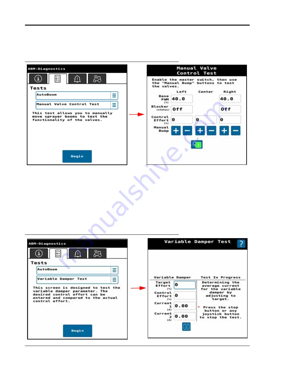
MANUAL VALVE CONTROL TEST

The Manual Valve Control test allows the user to manually move the sprayer booms to validate hydraulic valve 

function.

FIGURE 18. Manual Valve Control Test

VARIABLE DAMPER TEST

The Variable Damper test allows the user to manually apply a control effort to the variable damper system.
1. Select 

Connectivity Test

.

2. Enter a 

Target Effort Percentage

.

3. Touch the 

Start

 button.

NOTE:

Variable Dampers are optional. Test is only valid if equipped.
Each damper should draw between 2.0 and 2.8 amps when tested at 100%.

FIGURE 19. Variable Damper Test

Summary of Contents for Case IH AutoBoom XRT

Page 1: ...Copyright 2020 2021 Case IH AutoBoom XRT Calibration Operation Manual 016 0235 002 Rev B 12 2021 E40048 ...

Page 2: ...aven Industries shall not be held responsible for any modifications or repairs made outside our facilities nor damages resulting from inadequate maintenance of this system As with all wireless and satellite signals several factors may affect the availability and accuracy of wireless and satellite navigation and correction services e g GPS GNSS SBAS etc Therefore Raven Industries cannot guarantee t...

Page 3: ...e Screen Operation 8 Master Switch 9 Sensitivity Settings 9 Target Height Settings 9 Height Sensory Sensitivity 10 Target Type 10 Manual Auto 11 Sensor Reading 11 AutoBoom XRT Operation on Raven Operating Software ROS 12 Run Screen Operation 12 AutoFold Operation 13 AutoFold Out to Spray Position 13 AutoFold In to Transport Position 13 Chapter 4 Calibration 15 First Time Configuration 15 Chapter 5...

Page 4: ...ystem Gain 47 Chapter 7 Diagnostics and Troubleshooting 49 System Information 49 Boom Outputs 49 Fold Outputs 50 Boom Readings 50 CAN Bus Information 51 Fold Controls 51 Fold Sensor Readings 52 Hardware Software ABM 52 Height Sensor Readings 53 Machine Readings 53 System Hours 54 System Voltages 54 Variable Damper Outputs 55 Tests 55 Target Control Effort Test 55 Target Velocity Test 56 Target Pos...

Page 5: ...e influence of alcohol or an illegal substance Be alert and aware of surroundings and remain in the operator seat at all times when operating this Raven system Do not operate the implement on any public road with this Raven system enabled Disable this Raven system before exiting the operator seat Determine and remain a safe working distance from obstacles and bystanders The operator is responsible...

Page 6: ...ge hydraulic components Stand clear of the implement when starting the system for the first time after installing or servicing hydraulic components in case a hose has not been properly connected or tightened ELECTRICAL SAFETY Always verify that power leads are connected to the correct polarity as marked Reversing the power leads could cause severe damage to the Raven system or other components To ...

Page 7: ...ree limbs fence posts crop stubble dirt clumps or rocks that may fall or be thrown by the implement Protect hoses from sharp bends twisting or flexing over short distances and normal implement operation Ensure sufficient length for free movement of the implement during normal operation and prevent pulling pinching catching or rubbing especially in articulation and pivot points Clamp hoses securely...

Page 8: ...CHAPTER 1 4 Case IH AutoBoom XRT Calibration Operation Manual ...

Page 9: ...ood safety practices Be sure to carefully read the instructions in this manual as you complete the installation process Raven Industries recommends the following best practices when installing or operating the XRT system for the first time at the start of the season or when moving the AutoBoom XRT system to another machine Verify that the machine s hydraulic system is using fresh oil and that the ...

Page 10: ... will help shape the future of our product documentation and the overall service we provide We appreciate the opportunity to see ourselves as our customers see us and are eager to gather ideas on how we have been helping or how we can do better To serve you best please send an email with the following information to techwriting ravenind com Case IH AutoBoom XRT Calibration Operation Manual 016 023...

Page 11: ...REEN AND OPERATION UT OPERATION Pressing the UT widget on the run screen will open the UT interface From this screen it is possible to adjust machine settings view diagnostic information and adjust Sensitivity and Target Height FIGURE 1 UT Run Screen Interface ...

Page 12: ...o access AutoBoom XRT screens 1 Press the UT icon FIGURE 2 Home Screen 2 Select the XRT working set icon XRT HOME SCREEN OPERATION FIGURE 3 XRT Home Screen Settings Home Diagnostics Totals XRT Sensor Reading Manual Auto Sensitivity Target Height Sensitivity Settings Master Switch Target Type Target Height Settings ...

Page 13: ... folded position SENSITIVITY SETTINGS Use the Sensitivity Settings buttons to increase or decrease the system sensitivity Increasing the sensitivity will increase how quickly the boom responds to the sensor target Increasing the sensitivity too high may result in unnecessary or excessive movement Decreasing the sensitivity will result in less boom movement but will make the booms slower to respond...

Page 14: ...etecting a canopy however as the Height Sensory Sensitivity value increases drift suppression decreases The Height Sensory Sensitivity value is set to 45 by default TARGET TYPE FIGURE 5 Target Type Press the Target Type to select between the desired measurement target Ground This target type will use the ground signal as the primary target but will use the canopy signal if it has a higher confiden...

Page 15: ... Switch on the system is ready to engage Another way to switch from Manual Auto is to press on the desired boom section SENSOR READING Sensor Height displays the height for each of the sensors The number of sensors displayed will match the number of sensors on the machine The table below describes the Sensor Height reading in more detail TABLE 1 Sensor Reading States Image Status Description Senso...

Page 16: ... RUN SCREEN OPERATION FIGURE 6 Run Screen 1 Press the desired boom on the XRT widget to enable or disable AutoBoom XRT 2 Press and hold the desired widget to open additional boom information Pressing and holding also allows the user to turn on or off the master switch FIGURE 7 XRT Widget Long Hold ISO AutoBoom Widget ...

Page 17: ... any time to abort the AutoFold cycle FIGURE 8 AutoFold Button 2 Release the AutoFold switch after the boom has reached the spray position AUTOFOLD IN TO TRANSPORT POSITION 1 Press and hold the AutoFold switch in the DOWN position NOTE Release the AutoFold switch at any time to abort the AutoFold cycle 2 Release the AutoFold switch after the boom has reached the transport position FIGURE 9 AutoFol...

Page 18: ...ion as the new target for folding OUT operation This setting affects tilt only The target positions for inner outer fold joints and the center rack position are not updated Update Cradle Position Recalibrates the boom tilt cradle position based on current boom position Boom should be resting in cradle The target positions for inner outer fold joints and the center rack position are not updated FIG...

Page 19: ...upon configuration settings and installed unlocks the following steps may vary After installing the XRT system 1 Park the machine on a level surface 2 Machine Make Machine Model and Machine Configuration will automatically populate into the three fields FIGURE 1 Machine Selection 3 Press Next ...

Page 20: ...he AutoFold feature is unlocked AutoFold will be calibrated at this time Refer to the AutoFold Calibration section on page 36 for assistance with calibrating the AutoFold system Once the AutoFold calibration is complete proceed with step 6 to continue the AutoBoom XRT calibration 6 Verify the orientation of the ABM ECU on the machine matches the downward forward orientation of the controller on th...

Page 21: ...ain Compensation 11 After terrain calibration compensation is complete press Next NOTE If the AutoFold feature is unlocked and calibrated the following steps will have been completed during the AutoFold calibration Skip to step 17 to continue the calibration process 12 Fold the boom in so the booms are stored in the transport position 13 Touch the Next button to continue fold calibration 14 Raise ...

Page 22: ...anual 15 Move the booms to a typical spray position The center rack should be well below the travel stops and the inner booms unfolded 16 Touch the Next button to continue the fold calibration FIGURE 6 Vertical Center Sensor Calibration Set to Spray Position ...

Page 23: ... generally a horizontal steel pin FIGURE 7 Center Rack Setup 18 Press Next 19 Enter the Z offset from the bottom of the spray tips to the bottom of the sensor lens for the identified sensor into the Offset Z field 20 Enter the X offset from the boom pivot point not the machine center line to the sensor mounting location into the Offset X field FIGURE 8 Height Sensor Setup 21 Press Next 22 Repeat s...

Page 24: ...2 4 m from the ground 24 Press Next FIGURE 9 Height Sensor Setup Set Booms Parallel 25 Raise the left boom until there is at least a 40 in 101 6 cm change in height 26 Press Next FIGURE 10 Height Sensor Setup Raise Left Boom 27 Raise the right boom until there is at least a 40 in 101 6 cm change in height ...

Page 25: ...If an IMU Inertial Measurement Unit is installed on the machine skip to step 32 30 Lower and level the booms 31 Have an assistant manually rock the boom up and down until the Next arrow appears The Next arrow will only appear when the voltage is more than 0 25 V apart FIGURE 12 Center Rack Rotation ...

Page 26: ...libration sequence to determine the duty cycle required to keep the boom stationary 34 If prompted manually raise or lower booms and press Next to continue calibration 35 Review the information on the Height Sensor Setup page 36 Press Next 37 Review the information on the System Summary page 38 Press Next 39 The XRT Home screen will be displayed NOTE If features are not visible on the XRT Home scr...

Page 27: ...CHAPTER 5 016 0235 002 Rev B 23 CHAPTER5SETTINGS MACHINE SETTINGS FIGURE 1 Machine Settings FIGURE 2 Machine Settings Drop down Menu ...

Page 28: ...aise or lower the center rack based upon height sensor readings FIGURE 3 Boom Configuration DISPLAY CONFIGURATION The Display Configuration window allows the user to create a customized view of the AutoBoom XRT home screen This may be useful for diagnostics and troubleshooting To configure the display 1 Select Display Configuration from the Machine Settings tab A window will open that represents t...

Page 29: ...itions instead of the AutoBoom sensor readouts on the AutoBoom XRT Main screen FIGURE 5 AutoFold Percentage Position Display 6 Select the Enable Disable Readout option at the bottom of the page to replace sensor readings on the AutoBoom XRT Main screen with large Auto Manual toggle buttons This can help the operator more easily confirm whether a boom fold section is engaged or not during AutoBoom ...

Page 30: ...tween the spray tip and the lens of the height sensor If the sensor is below the spray tip the Mount field should be set to Below FIGURE 8 Height Sensor Configuration Select the different sensors shown on the sprayer boom to modify that sensors configuration HEIGHT SENSOR UPDATES The Height Sensor Updates window allows the user to update software on the height sensors The sensors may be updated in...

Page 31: ...two sensors that were swapped Once both are selected touch the Swap button FIGURE 10 Swap Sensors REM UPDATES The REM software is included with the ABM software and updated through the object pool REM Updates window allows the user to update software If an update is available select reprogram No external file is needed for updating REM FIGURE 11 REM Update Swap ...

Page 32: ...boom will have its own settings from each preset selected FIGURE 12 Preset Configuration 3 Select the desired Preset Mode a Spray Mode Standard XRT operation mode b Preset 1 User customizable mode c Preset 2 User customizable mode 4 Select the Trigger Method a There is one trigger method per Preset mode 5 Select the Control To option a Height The preset will control to a user selected height b Ang...

Page 33: ... Base Duty Cycle Height Deadband and PID gain settings Use the Boom Gains and Boom Speed Tuning buttons to toggle between the two screens NOTE Pressing the Reset Tuning or Reset Gains buttons only reset the values displayed on that page The values are reset to defaults specific to your machine Make Model and Boom Width Refer to Chapter 6 AutoBoom XRT Advanced Tuning for additional information on t...

Page 34: ...nd to faster movements during manual boom movement 2 Base Duty Cycle Lift Only is the Duty Cycle required to hold the booms level stationary Changing this value does not effect the equivalent value for AutoBoom 3 Min and Max values set the maximum and minimum duty cycle that will be applied to the specified joint when the system is AutoFolding In or Out The Min Max values do not affect manual fold...

Page 35: ... increase in height at each step the system learns which sensor is at each location on the boom 1 Verify the number of height sensors detected matches the number installed on the machine 2 If all sensors are detected touch the Next button to continue FIGURE 16 Height Sensor Setup Sensor Indexing 3 Unfold the boom and set the booms to level and less than 8 ft 2 4 m above ground 4 When both booms ar...

Page 36: ...above 8 ft 2 4 m the Next button will be displayed Touch the Next button to continue FIGURE 18 Height Sensor Setup Raise Left Boom 7 Raise the right boom 8 When all sensors on the right boom have been raised above 8 ft 2 4 m the Next button will be displayed Touch the Next button to continue FIGURE 19 Height Sensor Setup Raise Right Boom ...

Page 37: ...e Duty Cycle required to keep the booms level FIGURE 21 Base Control Effort Calibration 1 Ensure the area around the machine is clear of bystanders and obstacles The booms will move up and down during this procedure 2 Unfold the booms fully and set the left and right booms level The booms must be within 5 of level to proceed with calibration 3 Toggle the master switch to the on position 4 Touch th...

Page 38: ...e machine needs to be parked on a level surface prior to performing this calibration FIGURE 22 AutoBoom Node Orientation BOOM ANGLE CALIBRATION LEFT AND RIGHT The Boom Angle Calibration button allows the user to recalibrate the boom tilt sensors This correlates the tilt sensor measurement to an angular boom position 1 Set the booms parallel and under 8 ft 2 4 m from the ground 2 Press Next FIGURE ...

Page 39: ...at least a 40 in 101 6 cm change in height 4 Press Next FIGURE 24 Height Sensor Setup Raise Left Boom 5 Raise the right boom until there is at least a 40 in 101 6 cm change in height 6 Press Next FIGURE 25 Height Sensor Setup Raise Right Boom 7 Lower and level the booms ...

Page 40: ...t the center angle icon will be used to calibrate the IMU FIGURE 26 Center Rack Rotation AUTOFOLD CALIBRATION AutoFold Calibration recalibrates the sensors used for performing automatic folding and fore aft operations This should be performed if sensors have been adjusted replaced or if AutoFold is not completing an AutoFold IN or AutoFold OUT sequence 1 Fold the boom and lower the booms completel...

Page 41: ...dle lips and inward to contact the vertical stops The Booms will control to the set point when cradling FIGURE 28 3 Unfold the left and right inner joints fully Leave the outer joints folded Tilt the booms down to the fullest travel extent FIGURE 29 Minimum Height ...

Page 42: ...ual 4 Unfold the left and right outer joints fully NOTE The booms may be raised up to complete this step FIGURE 30 Fold Tips Out 5 Raise the center rack to the maximum height and tilt the booms up to the full travel extent FIGURE 31 Raise Center Rack and Booms ...

Page 43: ...ime an AutoFold in operation is performed Left and Right tilt will not be relearned FIGURE 32 Set Booms and Center Rack to Spray Position RESET TO DEFAULTS Selecting Reset to Defaults allows the user to reset AutoBoom XRT to factory default settings To reset defaults 1 Press the Reset to Defaults button in the Calibrations screen FIGURE 33 Reset to Defaults NOTE Unlocks will not be erased during t...

Page 44: ... XRT Calibration Operation Manual ALARM SETTINGS The Alarm Settings tab provides the option to sound audible beeps from the display when AutoBoom transitions from Auto mode to Manual and Manual mode to Auto FIGURE 34 Alarm Settings ...

Page 45: ... a feature 1 Select Settings on the XRT home screen 2 Select the Unlocks tab 3 Select the padlock icon next to the feature to be unlocked 4 Enter the feature unlock code NOTE Dashes may be omitted letters may be entered in either upper or lower case 5 Touch the checkbox to submit the entered code NOTE A message will display indicating whether or not the unlock code that was entered is valid If the...

Page 46: ...CHAPTER 5 42 Case IH AutoBoom XRT Calibration Operation Manual ...

Page 47: ...ing with the hydraulic oil at normal operating temperature BASE CONTROL EFFORT CALIBRATION Accurate base control effort values are necessary for successful advanced tuning Only perform a Base Control Effort Calibration after warming the hydraulic oil If possible engage AutoBoom and drive slowly for two minutes prior to performing Base Control Effort calibration This will ensure the Solenoid coils ...

Page 48: ...FORT SCALE The boom speed to control effort scale value correlates the required PWM duty cycle to the hydraulic valve to create the desired boom speed To determine the boom speed to control effort scale 1 Select Diagnostics 2 Select Tests 3 Select Target Velocity Test FIGURE 2 Target Velocity Test 4 Press Begin Test 5 Set the Target Velocity to 2 per second 6 Raise the center rack with one boom lo...

Page 49: ...l the speed matches the target velocity 20 11 Repeat step 3 through step 10 for the other boom NOTE Test results are affected by solenoid coil temperature Perform the tests three or more times in rapid succession for best results DOWN SPEED RATIO Because of different flow restrictions and the affect of gravity booms generally lower faster than the raise for the same change in control effort Down s...

Page 50: ...decrease the Down Speed Ratio If the boom moved slower than the desired 2 per second increase the Down Speed Ratio value FIGURE 5 Down Speed Ratio Test Results 10 Repeat step 3 through step 9 until the speed matches the target velocity 20 11 Repeat step 3 through step 10 for the other boom NOTE Test results are affected by coil temperature Perform the tests three or more times in rapid succession ...

Page 51: ...height INTEGRAL GAIN Integral Gain I Gain compensates for changes in Base control effort over time This could be caused by oil temperature valve coil temperature boom weight or other system changes This is generally set between 0 001 and 0 003 To disable this feature set the value to 0 000 DERIVATIVE GAIN Derivative Gain D Gain prevents overshoot when moving the boom from one target position to an...

Page 52: ...CHAPTER 6 48 Case IH AutoBoom XRT Calibration Operation Manual ...

Page 53: ... TROUBLESHOOTING SYSTEM INFORMATION To access the System Information window 1 Select the Diagnostics icon 2 Select the System Information tab BOOM OUTPUTS The Boom Outputs window displays the Base PWM Blocker status and Control Effort FIGURE 1 Boom Outputs ...

Page 54: ...READINGS The Boom Readings window displays the boom position velocity and the Sensor Voltage of the selected boom Press the desired boom or center rack boom to view the information for that section Voltage and angular position should change smoothly through the range of movement Angular Position should be close to zero when the boom section is horizontal FIGURE 3 Boom Readings ...

Page 55: ...nformation about CAN system FIGURE 4 CAN Bus Information FOLD CONTROLS FIGURE 5 Fold Controls Manually control each section of the boom NOTE Depending upon your machine s configuration not all sections may be available to control on this page and some displayed sections may not be controlled via the displayed buttons ...

Page 56: ...ding for each fold joint If AutoFold is unlocked a percent position is also displayed 0 is fully folded and 100 is fully unfolded FIGURE 6 Fold Sensor Readings HARDWARE SOFTWARE ABM The Hardware Software ABM window displays the AutoBoom hardware and software number and versions FIGURE 7 Hardware Software ABM ...

Page 57: ... Serial Number Distance to Canopy Distance to Ground Canopy Confidence and Ground Confidence percentages for the selected sensor FIGURE 8 Height Sensor Reading MACHINE READINGS The Machine Readings window displays the current machine Speed Chassis Roll Position Chassis Pitch Position and Chassis Roll Rate FIGURE 9 Machine Readings ...

Page 58: ...EM HOURS The System Hours window displays the current Version Hours Version Engaged Hours Lifetime Hours Lifetime Engaged Hours FIGURE 10 System Hours SYSTEM VOLTAGES The System Voltages window displays the ECU Power and the Regulator voltages FIGURE 11 System Voltages ...

Page 59: ...2 Variable Damper Outputs TESTS TARGET CONTROL EFFORT TEST The Target Control Effort Test tests boom function with a static control effort Entering a Control Effort value equal to the Base Duty Cycle should result in no or very slow boom movement Higher values will cause the boom to raise and lower values will cause the boom to go down FIGURE 13 Target Control Effort Test ...

Page 60: ... tests an Average Velocity will display This should be within 20 of the Target Velocity If additional adjustments are required refer to AutoBoom XRT Advanced Tuning on page 43 FIGURE 14 Target Velocity Test TARGET POSITION TEST This test is designed to test the boom control PID loop Enter a target position several degrees away from the current position in the Target Angle field After running the t...

Page 61: ...ser is asked to run the engine at typical operating RPM The test reports a pass or fail for each engine speed If the test fails engine vibrations may be having a negative impact on system performance NOTE If the test fails check the node installation Verify the node is mounted securely and has not come lose during operation Also confirm that the node is mounted as instructed in the AutoBoom XRT ma...

Page 62: ...URE 18 Manual Valve Control Test VARIABLE DAMPER TEST The Variable Damper test allows the user to manually apply a control effort to the variable damper system 1 Select Connectivity Test 2 Enter a Target Effort Percentage 3 Touch the Start button NOTE Variable Dampers are optional Test is only valid if equipped Each damper should draw between 2 0 and 2 8 amps when tested at 100 FIGURE 19 Variable ...

Page 63: ...eration Active DTCs must be fixed before the XRT system can be enabled for operation Once a DTC has been corrected the code moves to the inactive DTC code list FIGURE 21 Diagnostic Trouble Codes Screen NOTE In Figure 21 on page 59 above the active DTC is 522951 04 and the DTC summary is Right Fold 1 Voltage Low The inactive DTC is 522947 03 and the DTC summary is Left Fold 1 Voltage High FIGURE 22...

Page 64: ...OWER VOLTAGE LOW 520194 4 LEFT LIFT POSITION VOLTAGE LOW 522946 4 ABM LOSS OF COMMUNICATION ON ABM XRT CANBUS 520457 31 LEFT LIFT POSITION VOLTAGE HIGH 522946 3 ABM LOSS OF COMMUNICATION WITH REM 522945 31 LEFT FOLD 1 POSITION VOLTAGE LOW 522947 4 LEFT FOLD 3 IN SOLENOID CURRENT LOW 522922 5 LEFT FOLD 1 POSITION VOLTAGE HIGH 522947 3 RIGHT FOLD 3 IN SOLENOID CURRENT LOW 522923 5 LEFT FOLD 2 POSITI...

Page 65: ...W 522938 5 CENTER LIFT POSITION VOLTAGE HIGH 522955 3 CENTER RACK RAISE SOLENOID CURRENT LOW 522939 5 LEFT OUTER HEIGHT SENSOR OFFLINE 522956 31 CENTER RACK LOWER SOLENOID CURRENT LOW 522940 5 LEFT OUTER HEIGHT SENSOR NEEDS UPDATE 522956 1 DAMPER 1 DRIVER CURRENT LOW 520168 5 LEFT INNER HEIGHT SENSOR OFFLINE 522957 31 DAMPER 2 DRIVER CURRENT LOW 520169 5 LEFT INNER HEIGHT SENSOR NEEDS UPDATE 52295...

Page 66: ...FOLD 1 OUT SOLENOID CURRENT HIGH 522933 6 LEFT FOLD 1 IN OUT PRESSED 0 0 LEFT BLOCKER SOLENOID CURRENT HIGH 522934 6 LEFT FOLD 2 IN OUT PRESSED 0 0 LEFT PROPORTIONAL SOLENOID CURRENT HIGH 522935 6 LEFT FOLD 3 IN OUT PRESSED 0 0 RIGHT BLOCKER SOLENOID CURRENT HIGH 522936 6 RIGHT LIFT UP DOWN PRESSED 0 0 RIGHT PROPORTIONAL SOLENOID CURRENT HIGH 522937 6 RIGHT FOLD 1 IN OUT PRESSED 0 0 BOOM CRADLE LO...

Page 67: ...ID ABM ORIENTATION DETECTED 522964 31 ABM LOSS OF COMMUNICATION WITH UT 524082 31 TABLE 2 Radar LED Colors LED Status LED Color Sensor is in bootloader mode Flashing Red at 10 Hz Sensor is reprogramming Flashing Red at 1 Hz No CAN Communication Flashing Yellow at 10 Hz CAN Communication but no ABM detected Flashing Yellow at 1 Hz ABM detected but not indexed Flashing Pink at 1 Hz Sensor has been i...

Page 68: ...r Off Active when the microprocessor is not powered A Red 1 ISOBUS Offline Active if the ISOBUS is offline A White 1 ISOBUS Online Active if the ISOBUS is online A Green 1 Systems Normal Active when linked with VT and system is normal B Red 1 ECU Power Loss System has lost Logic power but not high current power B Off Solid ECU Has Power System has logic power and high current power C Red Solid FPG...

Page 69: ...mance window displays Deviation of Heights Average Terrain Average Error and Average Speed FIGURE 27 ABM Performance The Resettable Performance window shows the same information as the short term performance tab but allows the user to reset the information NOTE Press the Report Issue button to send out diagnostic information on the ISOBus You may be asked to do this if working with Tech Support To...

Page 70: ...CHAPTER 7 66 Case IH AutoBoom XRT Calibration Operation Manual ...

Page 71: ...er s responsibility The Return Materials Authorization RMA number must appear on the box and all documentation including proof of purchase must be included inside the box to be sent to Raven Industries WHAT WILL RAVEN INDUSTRIES DO Upon confirmation of the warranty claim Raven Industries will at our discretion repair or replace the defective product and pay for the standard return freight regardle...

Page 72: ... claim and send it to Raven Industries for final approval The freight cost to Raven Industries will be the customer s responsibility The Return Materials Authorization RMA number must appear on the box and all documentation including proof of purchase must be included inside the box to be sent to Raven Industries In addition the words Extended Warranty must appear on the box and all documentation ...

Reviews: