Use and maintenance manual Touch Radio Hydro
Pag.26
Rev.0 18/05/2021
EN
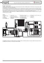
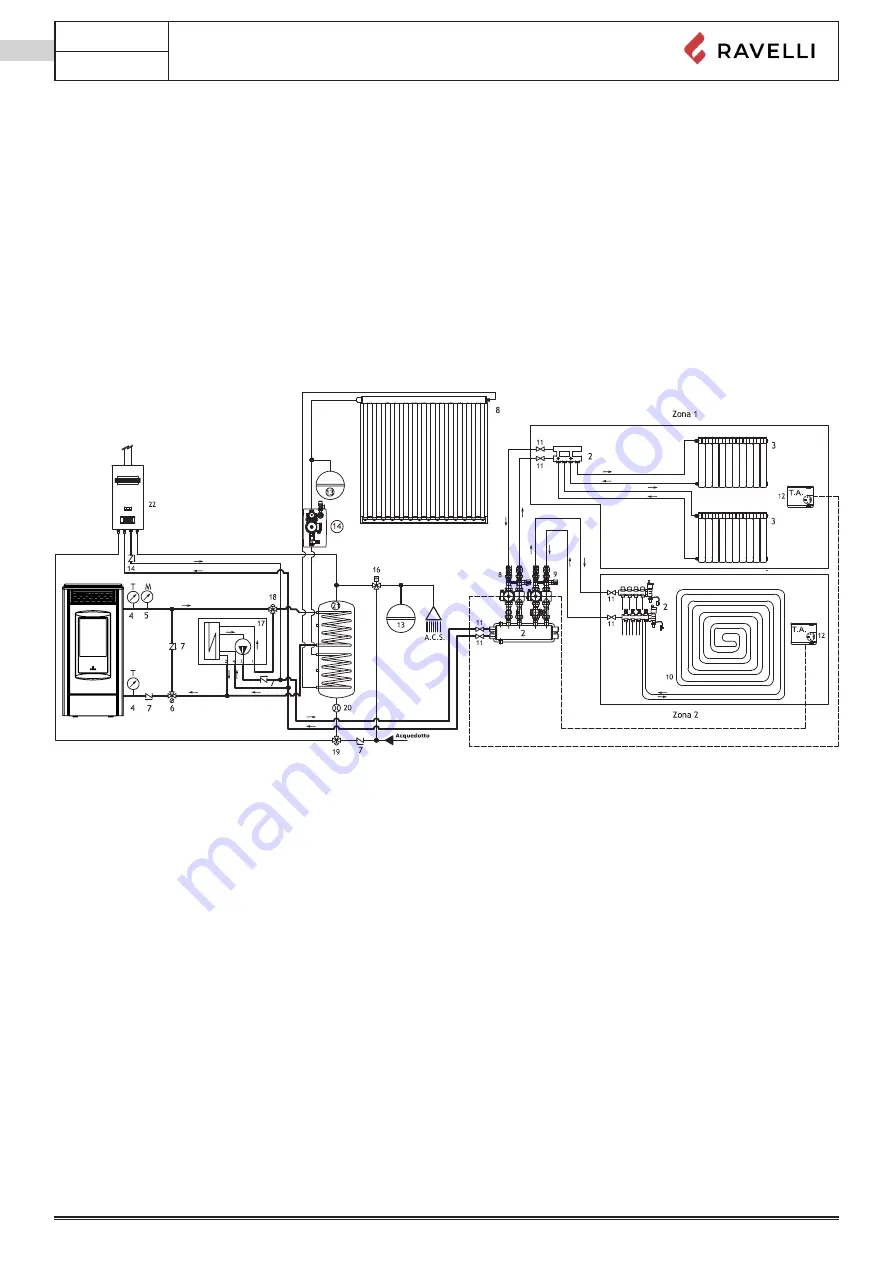
Diagram 1 (boiler sensor)
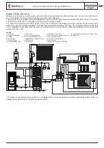
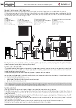
Diagram 1 allows operating a heating system where there is also a boiler for DHW production. The boiler can be connected to other
heat production units, such as solar panels.
With this diagram, the stove operates to bring the boiler to the set temperature; when the set water temperature is reached, the three-
way valve changes position and the thermo-stove begins to exchange heat in the heating system. From now on, the boiler is operated
by an external thermostat or by the internal H2O set (as in diagram 0). The thermo-stove reheats the boiler once the boiler water
temperature has fallen below the set-point value or when the flow switch (if connected) detects DHW being used.
If the thermo-stove is in ECO STOP mode or in WATER STAND-BY mode, a request by the Boiler of flow meter is added to diagram
0 standard start-up conditions.
The diagram shown here is indicative and may not display all the components required to properly operate the system. Rely on a
qualified thermal technician for the hydraulic system design.
Stufa a Pellet
LEGEND
1- Pellet stove
2- Distribution manifolds
3- Radiators
4- Thermometer
5- Pressure gauge
6- Anti-condensation valve
7- Check valve
8- Group of direct distribution
9- Thermostatic distribution unit
10- Radiant panel (underfloor heating)
11- Shut-off valve
12- Thermostat
13- Expansion vessel (tank)
14- Pump station for solar thermal system
15- Solar thermal collector
16- Thermostatic mixing valve
17- Power separation system
18- Motorised three-way valve
19- Motorised three-way valve with spring return
20- Flow switch
21- DHW storage
22- Gas boiler
Summary of Contents for Hydro
Page 3: ......
Page 54: ......
Page 55: ......
Page 106: ......
Page 107: ......
Page 108: ......
Page 110: ...USE AND MAINTENANCE MANUAL HYDRO Handheld Touch Radio Hydro...
Page 111: ......
Page 162: ......
Page 163: ......
Page 164: ......
Page 166: ...BEDIENUNGS UND WARTUNGSHANDBUCH HYDRO PDA Touch Radio Hydro...
Page 167: ......
Page 218: ......
Page 219: ......
Page 220: ......
Page 222: ...MANUAL DE USO Y MANTENIMIENTO HYDRO Dispositivo Touch Radio Hydro...
Page 223: ......
Page 274: ......
Page 275: ......
Page 276: ......
Page 278: ...HANDLEIDING VOOR GEBRUIK EN ONDERHOUD HYDRO Handheld Touch Radio Hydro...
Page 279: ......
Page 330: ......
Page 331: ......
Page 332: ......


