background image

Operating Instructions D50+ | P50+ | SHERAprint 50  


53 

 96 

Rapid Shape GmbH 

 DOCR000438 


Enabling the 

Show detailed printing 

screen


Proceed as follows if you want the detailed print view with force charts 
to be displayed as standard during printing: 

1.


Access the 

«

Customer

»

 menu: Main Menu > 

«

Setup

»

 > 

«

Service

»

 > 

«

Switch Level

»

 > 

«

Customer

»

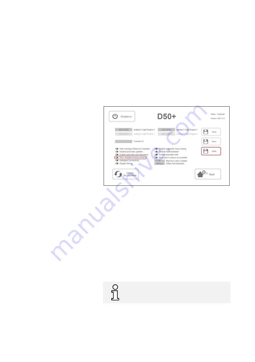
. (see fig. below) 

2.


Locate the button 

«

Show detailed printing screen

»

 on the left-

hand side of the display. 

The button lights up red when the 

function is disabled.


3.


Press the button next to the description to enable the function. 

The button lights up green when the function is enabled.


4.


Press the 

«

Save

»

 button on the right-hand side of the display to 

save the setting. 

5.


Return to the main menu. 


Figure 22: Customer menu

, „Show detailed printing screen“


7.8.3


Pausing Jobs & Ending Them Prematurely 


You can pause or prematurely end an active printing process (for 

example, in the case of a failed or incorrect job). 

Pausing a Job 

Proceed as follows to pause a job: 

1.


Progress summary: Press the 

«

Pause

» 

button. The current layer is 

still cured in full, then the printing process is stopped. 

2.


Press the 

«

Continue

»

 button to resume the paused printing 

process. 

Ending a Job 

Proceed as follows to end your print job: 

1.


Progress summary: Press the 

«

Cancel

»

 button. The printing 

process is cancelled immediately and you return to the main 
menu. 


We do not recommend pausing the print job or not for 
too long as the interrupted layer may not adhere 
properly due to too much exposure to oxygen. 


Summary of Contents for D50+

Page 1: ...P50 SHERAprint 50 Translation of the Original Operating Instructions Rapid Shape GmbH R merstra e 21 71296 Heimsheim Germany Phone 49 0 7033 309 878 0 info rapidshape de www rapidshape de Revision 1 1...

Page 2: ...ition the local health and safety regulations and general safety regulations apply to the area of application of the machine Redistribution and duplication of this document utilization and communicati...

Page 3: ...Requirements 17 1 7 Personal Protective Equipment 18 1 8 Environmental Protection 18 2 Overview 19 2 1 Machine Assembly Operating Elements 19 2 2 Serial Plate 22 3 Transport Storage 23 3 1 Transportin...

Page 4: ...7 5 9 Enable Automatic Refill 41 7 5 10 Move Jobs in Queue on complete 42 7 5 11 Maximum Jobs in Basket 42 7 5 12 Offset Part Detection 42 7 6 Preparing the Machine for Printing Start of the Day 43 7...

Page 5: ...d Period of Time 1 Week 67 8 2 Shutting Down the Machine for a Long Period of Time 1 Month 67 9 Troubleshooting 68 10 Cleaning Maintenance 69 10 1 Overview of the Cleaning Maintenance Work 69 10 1 1 C...

Page 6: ...Operating Instructions D50 P50 SHERAprint 50 Rapid Shape GmbH DOCR000438 6 96 12 1 Operating Data 96 12 2 Dimensions Weights 96 12 3 Connections 96 12 4 Serial Plate 96...

Page 7: ...jury if not avoided CAUTION This combination of symbol and signal word indicates a potentially dangerous situation which may lead to minor or slight injuries if not avoided NOTE This combination of sy...

Page 8: ...n to particular dangers the following symbols are used in safety notices Warning Dangerous electrical voltage Warning Hand injuries Warning UV radiation Warning Pointed objects Warning Hot surfaces Ti...

Page 9: ...n within potentially explosive areas Operation with explosion hazardous printing materials Outdoor operation Operation in tropical climates Operation in wet damp rooms Operation without sufficient ins...

Page 10: ...vice 2 Hood switch Chapter 1 3 2 Safety device 3 Knife protection device Chapter 1 3 3 1 3 1 Protective Hoods The protective hoods on the printer protect against direct contact with the live electrica...

Page 11: ...topped If the knife protection device is opened during the printing process it is stopped immediately and paused until the knife protection device is closed again and the safety warning on the touch d...

Page 12: ...h this symbol can be live Work in these areas may only be carried out by qualified electricians Hand Injuries The build area of the machine marked with this symbol consists of moving parts among other...

Page 13: ...ualified electricians and in compliance with the relevant safety and VDE regulations Machines with damage to the power cord insulation or lack of earthing must be disconnected from the mains immediate...

Page 14: ...are to the source of radiation the more critical the radiation can be that is emitted by the exposure unit You should therefore avoid looking into the UV radiation for an extended period at build are...

Page 15: ...spective manufacturer Please take note of the safety data sheets for the respective materials 1 5 5 Danger due to Hot Surfaces CAUTION Risk of injury due to hot surfaces The hot air fans in the machin...

Page 16: ...tions may result in property damage to the machine Protect the machine from moisture dripping water and splashing water Protect the machine from dust in excessive quantities Protect the machine from h...

Page 17: ...he personnel at a fixed location near the machine regularly inform all persons who work with the machine about the current general accident protection guidelines The operator must ensure that precauti...

Page 18: ...the personal protective equipment UV Protective Goggles Wearing UV goggles protects the eyes from harmful UV radiation Protective Gloves Wearing protective gloves protects the skin from contact with s...

Page 19: ...gure 1 Machine overview front back 1 Frame 10 Middle hood 2 Upper hood protective hood 11 Air outlet 3 Touch display 12 Ethernet connection 4 Hood handle 13 USB port 5 USB port 14 Main switch Toggle s...

Page 20: ...ape GmbH DOCR000438 20 96 Figure 2 Machine overview build area 17 Collection basket 23 Hot air fan heating function 18 Material reservoir 24 Knife protection device 19 Reference plate 25 Knife Drip gu...

Page 21: ...iew build area middle hood 26 Knife 33 Material bottle 27 Build platform 34 Bottle holder material 28 Build platform splash guard 35 Bottle holder isopropanol 29 RFID spot front 36 Response range foot...

Page 22: ...Platform 42 Splash guard handle 39 FRONT marking 40 Knurled thumb nut Figure 5 Knife Knife Drip guard 43 Blade 47 Knife Drip guard 44 Locating pin 48 Retaining collars 45 Carrier plate 46 Knurled thu...

Page 23: ...ed qualified personnel Before commencing transport attach suitable securing devices to the lifting and transport equipment to secure the transport box against falling over Never transport the machine...

Page 24: ...same process on the other side of the machine 10 Loosen both arresters on the front two castors on the machine 11 Now move the machine slowly and carefully down the ramp onto the ground Note Risk of...

Page 25: ...for a prolonged period store the machine in a dry dust free and frost protected room on a horizontal and stable base with all hoods closed best secured in the original transport box using lashing str...

Page 26: ...pressed air supply max 2 bar 4 1 2 Setting Up the Machine Figure 9 Spirit levels For setting up the machine please proceed as follows 1 Prerequisite The machine has already been fully connected Chapte...

Page 27: ...o fit them to the machine 2 Wear protective gloves on your hands 3 Open the upper hood 4 Preparations Remove the collection basket and place it on a paper towel Caution Watch out for material dripping...

Page 28: ...king nuts again 15 Repeat this process for the remaining castors until all the shims required have been fitted 16 Afterwards check that the machine is in a horizontal position The air bubbles on both...

Page 29: ...mains in case of an emergency by pulling out the mains plug Chapter 5 Keep moisture away from live parts This may lead to short circuiting Figure 11 Connecting the machine Please proceed as follows t...

Page 30: ...lay to open the Windows Action Centre 2 Press the Network button 3 If not switched on enable the Wi Fi function by pressing the Wi Fi button 4 Touch the display anywhere to close the Action Centre 4 2...

Page 31: ...ed 3 Acknowledge the emergency stop in the sequence indicated on the touch display Pull and rotate the emergency stop button out of the activated position Press the Shutdown button The machine is shut...

Page 32: ...job you need the following print accessories 1 Build platform 1 Material reservoir Printing material in original container Up to date information on printing materials such as safety data sheets tech...

Page 33: ...The slicing software Netfabb is needed for further processing your print file Install Autodesk Netfabb from the USB stick supplied in delivery and follow the installation instructions on the inside o...

Page 34: ...he printer software opens and the start page main menu of the user interface is displayed see fig below The z axis carries out a reference run in the direction of the upper end position 3 Verify the m...

Page 35: ...art page main menu of the user interface is displayed see fig below The z axis carries out a reference run in the direction of the upper end position 3 Verify the machine status Chapter 7 2 Figure 14...

Page 36: ...LED that indicates the various machine statuses The individual signal colours and signal types are described below Colour Signal Type Description permanent Idle state machine is ready for operation p...

Page 37: ...ill move downwards until it is closed flush with the housing 7 4 2 Opening Closing the Machine manually Hood Assistant The top protective hood on the machine can be opened and closed manually The addi...

Page 38: ...e fig below 2 Locate the button Disable automatic hood closing in the centre of the display The button lights up green when the function is enabled 3 Press the button next to the description to disabl...

Page 39: ...ustomer menu Main Menu Setup Service Switch Level Customer 2 Locate the button Hide warnings reservoir inserted on the left hand side of the display The button lights up red when the function is disab...

Page 40: ...d printing screen button To set the print view refer to the separate chapter Switching the Print View Chapter 7 8 2 7 5 5 Intelligent Connectivity The Intelligent Connectivity function facilitates com...

Page 41: ...the printing material from overly long exposure to light and dust the upper hood closes automatically after a certain time period without requiring any manual intervention on the part of the user Thi...

Page 42: ...he machine Thereby you can set the number of print jobs that can be collected in the collection basket until the basket needs to be emptied The number of print jobs can be set with the Maximum jobs in...

Page 43: ...and collection basket make sure you check the individual components and protective glass on the machine for cleanliness Proceed as follows to check the components for cleanliness 1 Check the protectiv...

Page 44: ...on device Grasp the knife protection device by the retaining tab and pull it towards your torso as far as it will go Now lift the device slightly and pull it completely out of the machine Pay close at...

Page 45: ...t point into the machine 4 Make sure that the knife holder is in reference position Main menu Manual Mode ASM Manual Mode 5 Read the warning shown on the display Confirm this by setting the confirm ch...

Page 46: ...Operating Instructions D50 P50 SHERAprint 50 Rapid Shape GmbH DOCR000438 46 96 Figure 19 Manual mode ASM Manual Mode...

Page 47: ...ial reservoir into the machine until the stop In doing so the reservoir is pulled slightly upwards and firmly fixed in place 3 If applicable the Reservoir Check message appears on the display Check th...

Page 48: ...m that you have performed the respective actions Depending on the selected actions the Reservoir Check messages are displayed the next time the reservoir is inserted A low level warning can be cancell...

Page 49: ...on the left hand side of the display The button lights up red when the function is disabled 3 Press the button next to the description to enable the function The button lights up green when the functi...

Page 50: ...separation function to OFF In this way the print job is not automatically separated after the last printed layer is completed and you need to remove the build platform manually to separate the print j...

Page 51: ...closed It is recommended to wear UV protective goggles whenever working on the machine NOTE Wearing UV goggles protects the eyes from harmful UV radiation During work steps in which the exposure unit...

Page 52: ...pter 7 10 2 Now manage the print job file You then return to the main menu We do not recommend opening the upper hood during the separation process since the immediate stop to the process can negative...

Page 53: ...side of the display to save the setting 5 Return to the main menu Figure 22 Customer menu Show detailed printing screen 7 8 3 Pausing Jobs Ending Them Prematurely You can pause or prematurely end an...

Page 54: ...are heated to the temperature required for the material up to 35 C Heating takes places by switching on two hot air fans in the machine build area The hot air fans switch on fully automatically provi...

Page 55: ...HERAprint 50 55 96 Rapid Shape GmbH DOCR000438 Figure 23 Manual mode Heating settings NOTE To avoid unnecessary wear make sure that the reservoir contact area is always dry and clean We recommend swit...

Page 56: ...ction basket and place it on a paper towel Caution Watch out for material dripping from the collection basket Hold the basket at a slight angle towards the back to prevent material from leaking out Al...

Page 57: ...pumping system when the level is too low 50 The function is disabled as standard when the machine is delivered To use the function a hose needs to be connected between the material bottle and the mate...

Page 58: ...on your hands 2 Open the material bottle and set the bottle cap aside 3 Place the opened material bottle in the bottle holder material The bottle holder prevents the bottle from tipping over when the...

Page 59: ...mpty bottle 5 Pull the stainless steel tube out of the empty bottle carefully and insert it into the new bottle immediately Take care that none of the material drips down 6 Take the empty bottle out o...

Page 60: ...ir Chapter 7 9 2 A reservoir with a low filling level 50 is inserted Re Pumping Printing Material Manually 1 In the main menu press the Manual Mode button 2 Press the Manual Refill button in Manual Mo...

Page 61: ...ve gloves on your hands 3 Open the upper hood 4 Remove the collection basket and place it on a paper towel Caution Watch out for material dripping from the collection basket Hold the basket at a sligh...

Page 62: ...knife protection device by the retaining tab and pull the guard towards your torso as far as it will go Now lift the guard slightly and pull it completely out of the machine Pay close attention to th...

Page 63: ...1 Wear protective gloves on your hands 2 Open the drawer on the x_wash cleaning unit 3 Place the individual components in the inner container The components must never touch the rotors and cover each...

Page 64: ...nts must not be stacked on top of each other and should not cast shadows over each other The maximum component height is not allowed to be exceeded 4 Close the lid 5 Select the operating mode and star...

Page 65: ...the printing material 1 Wear protective gloves on your hands 2 Spread out several paper towels on the work surface 3 Open the upper hood 4 Remove the collection basket and clean it Then set the cleane...

Page 66: ...ts back into the machine in the specified order Chapter 7 6 2 7 6 5 7 14 Machine Follow Up End of Day The machine needs to be cleaned at the end of the day Therefore the following steps need to be car...

Page 67: ...button The countdown is cancelled and you are taken back to the user interface Closing the Software You can close the printer software during the shutdown countdown to return to the machine desktop To...

Page 68: ...reservoir found Polymerised residues have been detected in the reservoir Remove the collection basket and then the reservoir from the machine Check the bottom of the reservoir for polymerised residue...

Page 69: ...rming automatic reservoir cleaning 10 1 11 As required Cleaning the hose 10 1 12 As required Changing the knife 10 1 13 As required Changing the hose 10 1 14 NOTE This work is only to be carried out i...

Page 70: ...1 Wear protective gloves on your hands 2 Open the upper hood 3 Remove the collection basket and place it on a paper towel Caution Watch out for material dripping from the collection basket Hold the b...

Page 71: ...els scalpel Preparation Proceed as follows to prepare for cleaning the build platform 1 Wear protective gloves on your hands 2 Spread out several paper towels on the work surface 3 Open the upper hood...

Page 72: ...ith paper towels afterwards 3 Use a scalpel to remove any hardened material residues 4 Check that the holes in the platform are free of residues 5 Reinsert the splash guard into the platform and then...

Page 73: ...ials Required Accessories Safety gloves isopropanol paper towels brush small brush optional Preparation Proceed as follows to prepare for cleaning the knife 1 Wear protective gloves on your hands 2 Sp...

Page 74: ...arp blade during cleaning Never rub quickly or against the blade 3 Turn the knife over and clean the other side Take care not to cut yourself on the knife s sharp blade during cleaning Never rub quick...

Page 75: ...d out several paper towels on the work surface 3 Open the upper hood 4 Remove the collection basket and place it on a paper towel Caution Watch out for material dripping from the collection basket Hol...

Page 76: ...ed for this purpose to avoid fingerprints on the glass bottom The material reservoir is an essential printing accessory Incorrect handling and the failure to provide the prescribed care can have a neg...

Page 77: ...on a paper towel 3 Fill isopropanol in the reservoir 4 By using a soft silicone spatula carefully mix the isopropanol with a back and forth motion to loosen the material residues from the bottom of th...

Page 78: ...be cleaned or alternatively changed each time the material is changed to avoid mixing different materials Required Accessories Safety gloves isopropanol paper towels brush small brush Execution For cl...

Page 79: ...m harmful UV radiation During work steps in which the exposure unit is active we always recommend wearing UV protection goggles To prevent components from sticking to the build platform incorrectly th...

Page 80: ...device into the machine 7 Take the sensor in your hand and remove the black rubber cap from the sensor head if present 8 Then place the sensor head in the calibration device with the glass surface fa...

Page 81: ...ns of wear Required Accessories Safety gloves isopropanol paper towels brush small brush Execution For checking the knife visually please proceed as follows 1 Wear protective gloves on your hands 2 Sp...

Page 82: ...ood 3 Insert the hose holder with the material feed hose into the parking position on the machine housing The end of the hose with the stainless steel nozzle must be pointing upwards Take care that no...

Page 83: ...ted are to be observed NOTE Wearing protective gloves protects the skin from contact with skin damaging materials During work steps in which you work with printing materials or cleaning agents we alwa...

Page 84: ...chine Chapter 7 6 2 9 Place a DIN A4 sheet of paper on the calibration plate to avoid possible scratches on the calibration plate caused by the dial gauge Execution For checking the parallelism of the...

Page 85: ...RAprint 50 85 96 Rapid Shape GmbH DOCR000438 8 Pull the calibration plate out of the machine and put it back safely into the packaging 9 Press the Home button to return to the main menu Figure 30 Adju...

Page 86: ...layer from the bottom of the reservoir If individual particles are also found floating in the printing material or material residues are found outside the build field area at the bottom of the reservo...

Page 87: ...ce the removed layer on a paper towel The bottom of the reservoir is now clean 8 Push the material reservoir back into the machine and close the upper hood 9 Dispose of the material layer as intended...

Page 88: ...a material change To avoid mixing materials and possibly colours the hose needs to be cleaned every time the material is changed We also recommend cleaning the hose before prolonged periods of non us...

Page 89: ...wel into the hose opening to soak up any isopropanol that drips out Carefully hang the hose down towards the floor 6 Pull the right hand end of the hose with the stainless steel tube out of the bottle...

Page 90: ...e hose with the stainless steel tube and insert it into the possibly newly material bottle provided 11 Press the pump cover down to fix the hose back in the pump 12 Insert the hose into the hose cut o...

Page 91: ...t Hold the basket at a slight angle towards the back to prevent material from leaking out Also place a paper towel directly underneath the basket opening 6 Open the knife protection device Grasp the k...

Page 92: ...Operating Instructions D50 P50 SHERAprint 50 Rapid Shape GmbH DOCR000438 92 96 8 Dispose of the used blade as intended according to local waste disposal regulations...

Page 93: ...of the hose holder guide Keep the end of the hose upright to avoid dripping material 9 Now pull the stainless steel tube out of the material bottle again keeping the end upright to avoid dripping mate...

Page 94: ...g Handle edged and pointed components carefully If necessary secure components so that they cannot fall down during work In case of doubt please contact the Customer Service CAUTION Risk of injury due...

Page 95: ...rdous to the environment Please dispose of machine parts and auxiliary materials in accordance with their intended use through your local recycling depot or approved specialist companies or return the...

Page 96: ...x Humidity 70 Altitude m up to 2 000 Pollution Level 2 All values are approximate 12 2 Dimensions Weights Width mm 625 Height mm 1 570 hood closed 1 985 hood opened Depth mm 443 Weight kg 130 All valu...

Reviews: