background image

Empty Density

: Permissible values are from 1 to 399.

Border

:  This is the border color.  Permissible values are:

BLACK
WHITE

Polarity

:  This is whether the image is to be printed as a negative or normally. 

Permissible values are:

NORMAL
REVERSE 
 

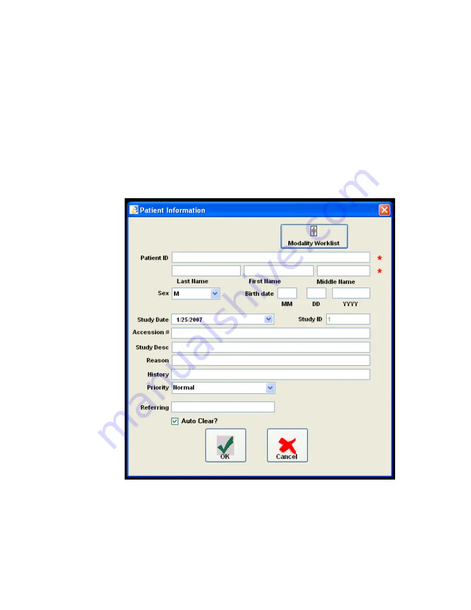
The procedure for image acquisition should begin with filling in the study information.


One should first click the button (or menu item) “Patient Info.  The following screen will 
then appear:

Figure 3-34 – Patient Information

The auto clear check box if checked will automatically clear the patient information 
upon a save study or send study event.  If not checked, the information will persist 
and not clear from study to study.

51

Summary of Contents for CR Pro

Page 1: ...CR Pro Computed Radiography CR Scanner USER MANUAL January 22 2007 Release 2 0 Reference Only Radlink Inc 2400 Marine Ave Redondo Beach CA 90278 310 643 6900 phone 310 643 6906 fax ...

Page 2: ...ity for any errors or inaccuracies that may appear in this book No part of this publication may be reproduced stored in a retrieval system or transmitted in any form or by any means electronic mechanical photocopying recording or otherwise without the prior written permission of Radlink Inc The following product names are trademarks of Radlink Inc CR Pro Pro Image Acquire Pro Image Viewer Pro Imag...

Page 3: ... sure the voltage selected matches the required voltage for the Model Domestic 97 140VAC 47 65Hz 15A Accommodates most of North and South America Eastern countries such as South Korea and Taiwan European 197 260VAC 47 60Hz 10A CR Pro European 240VAC 50Hz 3 0A Accommodates most of Europe the Middle East and the Far East LASER SAFETY The CR Pro is a Class 1 Laser Device which utilizes a 50 mW solid ...

Page 4: ... FM commercial broadcast television cellular services radar air traffic control pager and Personal Communication Services PCS These licensed services along with unintentional radiators such as digital devices including computers contribute to the electromagnetic environment While this device has been designed and determined to be compliant with regulatory agency limits for EMI there is no guarante...

Page 5: ...Do not dispose of the battery with household waste Contact a local waste disposal for the nearest battery disposal site REPLACING THE FLUORESCENT LAMPS There are four fluorescent lamps in the erase sub assembly Access to these lamps is very tight and care must be taken to avoid lamp breakage To replace a lamp perform the following 1 Turn off power to the device 2 Open the device back cover 3 Locat...

Page 6: ...to prevent the possibility of injected line noise by other devices The CR Pro is fused for 5 amp domestic and 3 amp European Fuses are located in the AC power input fixture on the back bottom right hand side of the CR Pro FUSE The input power is fused at the AC power input connector at the bottom right rear of the CR Pro cabinet The fuse s is located in a box directly above the input connector and...

Page 7: ...ION The packing crate can be tipped when shipping and moving and should be tethered to avoid tipping CAUTION The CR Pro weighs 198 pounds and even with attached casters to avoid injury it should not be moved by less than two people If lifted such lifting should be performed by professional movers or installers To remove the CR Pro from the shipping container 1 Remove the Philips head screws locate...

Page 8: ...ABLE OF CONTENTS Preface Chapter 1 Hardware Installation and Setup Chapter 2 Software Setup and Configuration Chapter 3 Operating Instructions Applications Gain Tables and Calibration Appendix Hardware Specifications Error Conditions and Actions USER QA CALIBRATION PROGRAM 8 ...

Page 9: ...rdous or illegal INSTALLATION Follow the Installation Instructions in this manual carefully Use only the supplied accessories If parts are missing contact eRadlink before proceeding PRESCRIPTION STATEMENT Federal law restricts the possession of this device to A person or his agents or employees regularly and lawfully engaged in the manufacture transportation storage or wholesale or retail distribu...

Page 10: ...e reliable operation Multiple file formats are supported including TIFF JPEG PNG BMP DICOM and Raw formatted images for both reading and writing Multiple images may be sent simultaneously to PACS hosts and the embedded DICOM Spooler handles multiple destinations and a DICOM broadcast capability The CR Pro has relatively few and connections making the installation process a quick and efficient proc...

Page 11: ...Chapter 1 Hardware Installation and Setup 11 ...

Page 12: ... Radlink Inc 2400 Marine Ave Redondo Beach CA 90278 Attn Customer Service 310 643 6906 fax 310 643 6900 phone Contents Table 1 CR Pro Hardware Quantity Description Part Numbers 1 CR Pro Scanner 02 00 001 2 Cassettes Phosphor Plate Holder 10in x 12in 14in x 17in with plates 1 Cable Power Cord 120 VAC 15A Or 1 Cable Power Cord 220 VAC 10A 1 Cable Ethernet 1 Cable USB2 Table 2 CR Pro Software Quantit...

Page 13: ...the back door remove the foam insert around the lead screw 2 With the back of the CR Pro facing you plug the output cable connector into the CR Pro Power Connector standard 3 pin female connector on the back of the CR Pro see Figure 1 2 3 Make sure the Power ON OFF switch see Figure 1 2 on the CR Pro is in the OFF position 4 Plug the male connector into a properly grounded A C power outlet It is d...

Page 14: ...Figure 1 1 CR Pro Scanner 14 Monitor CD RW LCD Display Keyboard Trackball Cassette Slot USB Port Ethernet Port On Off Switch AC Input AC Line Filter ...

Page 15: ...Figure 1 2 CR Pro Scanner Rear View Chapter 2 Software Setup and Configuration 15 ...

Page 16: ...ng are the installation procedures for updating the Radlink Application to the current Release 1 From Add Remove Programs in the control panel uninstall the Radlink application then reboot the computer 2 3 Double click the Double Click to Install Radlink Icon on the install CD This installs the Radlink application Simply inserting the Radlink CD will cause the setup program to be automatically run...

Page 17: ... or Large kVp The kVp setting at the X Ray machine mAs The milliamp seconds setting at the X Ray Machine Distance The distance between the X Ray tube and the X Ray cassette Grid Grid type Can be 103 178 or no grid Offset Should be set to calculate the Gain Gain Value This is the Gain Value as computed from the above settings 17 ...

Page 18: ...s that are not active Host Alias A user selected name for a PACS host This name can be modified by selecting the text in the Host Alias combo box and retyping a new name Changing the name will not impact DICOM communications Note that the Host Alias names are the names the user sees in the DICOM Spooler Host combo box IP Specifies Internet IP address Usually a World Wide Web address i e www radlin...

Page 19: ...on The compression techniques supported are noCompression Save the image uncompressed jpeglossy 8 bit Process 1 This is JPEG 8 bit lossy compression The default viewer with CD creation is only able to recognize jpeg 8 bit lossy and uncompressed images Destination Settings Action Buttons New A new host is created by pushing the New button A system generated Host Alias will automatically be generate...

Page 20: ...tion settings The DICOM Ping button is also present in the Radlink Router destination settings Router Settings The purpose of the Router Scheduler is to postpone DICOM transfers for example after business hours Figure 2 5 Radlink Router Scheduler When the check box is checked the router will cease to send images except between the times selected Figure 2 6 Scheduler Settings 20 ...

Page 21: ...ll not appear when the Send Status button is clicked This port is also utilized by Image Acquire for sending images to the router Figure 2 7 Raw Format Settings The Raw File Format settings define the settings for reading a file with no header information The Raw File Format defines the rows columns and depth of the raw bitmap image Raw Format Rows Number of rows in a Bit Map file Columns Number o...

Page 22: ...e Proxy server settings into the Radlink Fire Wall Settings If no settings are present and you have a Firewall contact your LAN administrator for the above settings It should be noted that the protocols being utilized by the Radlink system are TCP and SOAP The SOAP protocol uses an extended HTML packet header for communications Some firewalls do not allow HTML extensions If that is the case reques...

Page 23: ...lectable by clicking the check boxes as shown above Required Fields The fields on the Patient Information Screen can be set as Required Fields by the user of Image Acquire The settings for required fields can be found by clicking the SettingsàRequired Fields on the Image acquire main screen Figure 2 12 Required Fields Menu Item The following settings screen then appears Figure 2 13 Required Patien...

Page 24: ...cally between 4 and 10 for jpeg2000 lossless compression jpeg2000lossy This compression technique utilizes jpeg2000 wavelet lossy compression and achieves compression ratios between 10 and 70 The uncompressed images appear lossless in quality with this compression technique JPEG2000 will perform 8 12 and 16 bit compression jpeglossless This compression technique uses the common JPEG lossless compr...

Page 25: ...ever the default viewer with CD creation is only able to recognize jpeg 8 bit lossy and uncompressed images Overlay Settings Color and Font settings are provided for Calipers Annotation and Measurements One changes the color by selecting the Menu Item SettingsàOverlays Figure 2 15 Overlay Settings Menu The following settings screen then appears Figure 2 16 Overlay Settings On the above screen ther...

Page 26: ...mn The following screen then appears Figure 2 18 Font Picker The font picker displays all of the fonts and font sizes in the system Choose the desired font font style size and font effects then click OK In this example the color and font of the Annotation and Measurement settings have been changed to light blue Vladimir Script Figure 2 19 Modified Overlay Settings One should then save the settings...

Page 27: ...The following screen appears after selecting the Change Password menu item Figure 2 21 Change Password Dialog After the password has been set one must enter the password to change Radlink settings by logging into Radlink via the Login menu item If the password is not entered upon Radlink startup the Settings menu item will be disabled Figure 2 22 Password Login Screen 27 ...

Page 28: ...This is normally turned on Figure 2 23 Screen Settings Show Patient Info This displays or hides the patient information on the screen Show Caliper This displays or hides the caliper on the image Show Histogram This displays or hides the histogram This is normally turned off Show Overlays Overlays include the Annotation and measurements This is normally turned off 28 ...

Page 29: ...Chapter 3 Operating Instructions Calibration Application and Gain Tables 29 ...

Page 30: ...release of Radlink software you are working with click on Help on the top toolbar then click on About Radlink The release level will be displayed This is a necessary piece of information if you place an inquiry with Radlink customer service 310 643 6900 Release Level 1 4 2b1 cv2 200611021321 ONLINE HELP User Manual This user s manual can be displayed by logging in to www Radlink com CR Pro Phospho...

Page 31: ...ere is no right or wrong technique just guidelines for creating a uniform field 1 Start Application The Radlink application should be running if not select the Radlink application from the list of programs and start it on the CR Pro 2 Load Plate Scan Insert the exposed cassette in the CR Pro machine 3 Start Calibration Select the calibration selection under the TOOLS menu item 4 Calibration The CR...

Page 32: ...nk Main Screen To Acquire An Image The Main Screen is composed of seven action buttons under the title imaging workflow 1 Create Study 2 Create Series 3 Scan Image 4 QC Image 5 Change Info 6 Complete Study 7 Clear Study 32 ...

Page 33: ...ation Settings The Scan Image button Figure 3 4 Confirm X ray technique In this section you will select 1 The body part 2 The view 3 The patient s size 4 The technique kVp and mAs 5 Grid Type 178 recommended 6 Offset Calculate to set the Gain value 33 ...

Page 34: ...The Scan button The image is displayed line by line as it is scanned Figure 3 5 Image Scanning The scan button initiates scanning of the phosphor plate 34 ...

Page 35: ...tton The following screen will then appear Figure 3 6 Image QC This window will enable image processing enhancements Image information Processing Indicates the type of processing that has been applied to the image 35 ...

Page 36: ...low for different image positioning of the displayed x ray The Add Markers to Image buttons will ID image with the patient s Right and Left The Custom Marker button will enter script to image Personal Initials The Image Dimensions buttons will enable Crop to enhance image 36 ...

Page 37: ...ale to obtain a negative view of the image The Delete button Deletes the selected image Warning This permanently deletes the image such that it cannot be recovered The Finish button Saves the changes to the image and closes the QC window The Delete button will delete the selected image in the image series list The Clear button will delete all images on the screen 37 ...

Page 38: ...level sliders graphically displays the pixel distribution over the possible pixel values For a 16 bit image the maximum pixel value is 65536 For an 8 bit image the maximum pixel value is 256 Window Level can also be set by using the mouse with the right button depressed and dragging the mouse over the image Dragging the mouse horizontally will change the window setting Dragging the mouse verticall...

Page 39: ...ile Open Dialog shown in Figure 3 9 Files can be sent directly from the archive or any other selected directory To do this simply select the menu item FileàOpen Archive or FileàOpen Study from the Radlink main screen or select the FileàView Archive from the Radlink Router Figure 3 13 View Archive Screen 39 ...

Page 40: ... of the studies displayed Figure 3 14 Using the Study Filter In the above example the character c was typed into the patient name filter to narrow down the search to all patients whose name begins with c After the study or studies have been located select them and click the Send button to send them on to other PACS systems The following dialog will be presented Figure 3 15 Destination Selection 40...

Page 41: ...s that have been previously sent to PACS hosts one should select the menu item FileàOpen Archive This will bring up a open Study dialog pointed to the image Archive To save an Exam click the File à Save menu item The following dialog box will appear Figure 3 16 Selecting a Save Directory One navigates to the desired directory with the standard Windows File Open Dialog To create a new directory for...

Page 42: ...lder After creating the folder one should rename it and then navigate to it by clicking on it Figure 3 18 Navigating to the newly created save directory After the folder is created and selected for save as shown above Click the OK button 42 ...

Page 43: ...e The image as shown above is then added to the exam The image could be any standard JPG PNG TIF etc type image The image could also be a scanned document that is to be inserted into the study for referring doctor exam documentation When the exam is sent via the Send button the entire study including the newly added image is sent as a package One can also export any image in the study First select...

Page 44: ...r the JPG Lossy Compression technique The following dialog box will appear Figure 3 21 Image Save Dialog Choose any file name desired and click save Note that the File Type is predetermined and cannot be changed This file type was chosen in the previous step as shown in Figure 3 20 Figure 3 22 Studies Completed Report 44 ...

Page 45: ...alog One should click the button Enable Automatic Refresh This will ensure that the report has the current information Disk Management Screen The Archive Maintenance screen is activated by selecting the menu item FileàDatabase Maintenance Figure 3 24 Radlink Archive Maintenance 45 ...

Page 46: ...contents Please note that this capability previously was located on the destination settings screen The Backup Database button will backup the SQL database It is useful to periodically backup the database as most user settings are contained in the database The backed up database is called Backup and is located in the Radlink installation directory Typically c program files eRadlink backup The Dele...

Page 47: ...menu items are arranged in two groups The first group is for postscript printing Using the postscript requires that the printer be correctly configured One does this by selecting Print Setup which will produce the printer setup dialog Figure 3 26 Printer Setup 47 ...

Page 48: ... 27 Print Layout The print layout describes the image placement In this example there are to be 4 images per sheet of paper arranged in 2 rows and two columns One should then preview the images before printing by selecting Print Preview The images will then appear just as they would if actually printed One can now change the printer settings if necessary One then actually prints the images by sele...

Page 49: ...ain window The following are the permissible settings for the DICOM Printer Format This field specifies the layout of the images on the film The numbers at the end are the number of rows and columns Cropping These are Codonics True Size settings Permissible values are CROP DECIMATE FAIL NONE The value NONE will make the Radlink software not to send the crop decimate DICOM tag This choice was added...

Page 50: ...ssible values are BIN_1 BIN_2 BIN_3 BIN_4 BIN_5 BIN_6 BIN_7 BIN_8 BIN_9 PROCESSOR MAGAZINE Magnification Type Permissible values are REPLICATE BILINEAR CUBIC BICUBIC MITCHELL LANCZOS SHARP1 SHARP2 SHARP3 NONE Smoothing Permissible values are MEDIUM SHARP SMOOTH Trim This signifies whether or not to do cropping Permissible values are NO YES Min Density Permissible values are from 1 to 399 Max Densi...

Page 51: ...REVERSE The procedure for image acquisition should begin with filling in the study information One should first click the button or menu item Patient Info The following screen will then appear Figure 3 34 Patient Information The auto clear check box if checked will automatically clear the patient information upon a save study or send study event If not checked the information will persist and not ...

Page 52: ...should then press the Scan button which will send the images to the PACS system The Patient Search screen will allow one to automatically fill in the Patient Information by using patient information in the PACS database The following describes how to use this feature First click on the Patient Search button from the patient info screen The following screen appears Figure 3 35 Search Screen One sel...

Page 53: ...IP Internet IP address Usually a World Wide Web address i e www Radlink com IP can also be the physical network node address The physical network node address of Radlink is 65 117 85 195 Port Port is the logical port of the PACS server Client Title Client Title is the Client User Name This User Name is typically administered by the PACS host AE Title AE Host Title is PACS administered as well Sear...

Page 54: ...cquire The images scanned and saved by the Radlink Image Acquire application are burnable to CD using this facility To launch the CD Burner software one should either select the menu item FileàOpen Archive or FileàOpen Study menu item Figure 3 38 Selecting Exams for CD Burning 54 ...

Page 55: ...bel Database is used to retrieve studies from the CD Archive If you do not wish to save the Label information into the database then click the button Cancel Figure 3 39 Entering the CD Label After clicking Save Into Database the file copy to the CD process begins Figure 3 40 Adding Files to the CD One should ignore the windows pop up balloon that indicates that files are being written to the CD Fi...

Page 56: ... appear Figure 3 42 CD Writing Wizard Enter a name for the CD and click Next Figure 3 43 Burning the CD When the burning process is finished the CD will automatically eject One can then view the exams by inserting the CD The Radlink viewer will then be invoked 56 ...

Page 57: ...Figure 3 44 Patient List Figure 3 45 Opening an Exam With Radlink Image Acquire After navigating to the Exam on the CD click OK Then select the Exam to open and click Open Selected Study 57 ...

Page 58: ...nu item Settingsà Dicom File Settings Figure 3 46 Viewing the Exam With Radlink Image Acquire Figure 3 47 Dicom File Settings To utilize a different viewer when burning a CD enter the full path name of a viewer to burn rather than the Radlink provided viewer Entering in the full path name is facilitated with the folder button to the right which brings up a file navigation screen 58 ...

Page 59: ...arameters need to be entered PACS IP This is the IP of the PACS server PACS Port This is the port the PACS server listens for requests Typically the port is port 104 Client Title This is the name that the PACS system will need to return the r equested study Receive Port This is the port that the PACS system will return the study on The port number must be unique to the client machine After the cli...

Page 60: ...nations are displayed To enter a new destination click Add Enter the client side information such as IP Port and AE_Title information this should match the clent information entered in the Radlink System The information for this example is as follows Figure 3 50 Destination Identification 60 ...

Page 61: ...s the Client Title entered on the Radlink system After the communications settings are entered you can perform the Radlink Study Query Retrieve Click the Query button to get a list of all studies on the PACS server To filter the number of entries returned enter the first couple of letters of the patient name and or the first character or two of the patient ID and or the study date from to informat...

Page 62: ...ns entered for our example Figure 3 53 Router Destinations Now proceed to the Modality setup screen by clicking on the Modalities tab Figure 3 54 Router Modalities Now enter the port information and default destinations for each of the modalities routed 62 ...

Page 63: ...e configured to send to the IP that is defined on this machine the machine housing the modality router The AE title at the sending modality must be set to the Router AE Title The port setting in the example above is 1005 There cannot be duplicate modality AE Titles and the modality ports cannot conflict with other port settings within the machine The range of ports that can be assigned are from 1 ...

Page 64: ...nd The possible send status states are Preparing Images This indicates that the router is compressing the images for transmission Sending Images This indicates the router is currently sending the study The progress bar at the top of the screen shows the progress of the transmission for each image being sent in the study Retry In Progress If a transmission occurred the Router will retry the send fo...

Page 65: ...has been totally completed Senders Idle The Senders are idle and not sending images Figure 3 57 DICOM Router showing Resend and Delete Files Buttons on the Cancelled Screen Compression Decompression is also supported by the Radlink Router One should set the compression algorithm for each destination to perform the compression Figure 3 58 Radlink Router Destination Settings 65 ...

Page 66: ...ved and archived but not forwarded to any destination Changing the priority of a study is accomplished by first clicking on the desired study then changing the priority by clicking on the Study Priority combo box and choosing one of the three priorities Lastly an interface for performing Radlink Archive Database Maintenance functions is provided This screen is activated by clicking the menu item F...

Page 67: ...contents Please note that this capability previously was located on the destination settings screen The Backup Database button will backup the SQL database It is useful to periodically backup the database as most user settings are contained in the database The backed up database is called Backup and is located in the Radlink installation directory Typically c program files eRadlink backup The Dele...

Reviews: