Chapter 6 - Maintenance
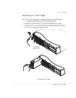
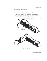
Replacing a DC Power Supply
79
Replacing a DC Power Supply
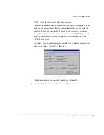
NOTE:
The DC power supply is hot-swappable. The storage system will continue to
function normally with one power supply during replacement.
1
Turn the On/Off switch to the “Off ” position on the affected power supply.
2
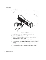
Disconnect the DC power cable. Squeeze the connector latches and pull the power
cable from the DC power cable module on the power supply.
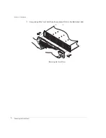
Releasing the Power Supply
SES CONTROLLER
PAR
T N
UMBER 08-9-96322001
AR
TW
ORK REVISION -1
JP1
JP2
RS-232
A
D
0
A
D
1
A
D
2
S
P
1
S
P
2
B
D
R
D
L
Y
R
M
T
SES
D1
DISK I/O
D2
Tx
Tx
Tx
Fibre
Disk IO
LRC
P/N
08-9
-96
318
001
A/W
Rev-1
INSTA
LL J
UMP
ERS
1 & 2
FOR
HAR
DWA
RE
FAIL
URE
DET
ECT
ADD
JUM
PER
FOR
1G O
PER
ATIO
N
JP2
JP2
JP3
JP1
ADD
JUM
PER
FOR
SPL
IT BU
S M
ODE
D1
DISK I/O
D2
Tx
Tx
Tx
Fibre
Disk
IO
LR
C
P/N
08-9
-9631
800
1
A/W
Rev-
1
INS
TAL
L JU
MPE
RS 1
& 2
FOR
HAR
DWA
RE
FAIL
URE
DET
ECT
ADD
JUM
PER
FOR
1G O
PER
ATIO
N
JP2
JP2
JP3
JP1
ADD
JUM
PER
FOR
SPL
IT B
US M
ODE
SES CONTROLL
ER
PAR
T N
UMBER 08-9-96322001
AR
TWOR
K REVISION -1
JP1
JP2
RS-232
A
D
0
A
D
1
A
D
2
S
P
1
S
P
2
B
D
R
D
L
Y
R
M
T
SES
D1
DISK I/O
D2
Tx
Tx
Tx
Fibre Disk IO LRC
P/N 08-9-96318001
A/W Rev-1
INST
ALL
JUMPERS 1 & 2
FOR HARDW
ARE
FAILURE DETECT
ADD JUMPER FOR
1G OPERA
TION
JP2
JP2
JP3
JP1
ADD JUMPER FOR
SPLIT
BUS MODE
D1
DISK I/O
D2
Tx
Tx
Tx
Fibre Disk
IO LRC
P/N 08-9-96318001
A/W Rev-1
INST
ALL
JUMPERS 1 & 2
FOR HARDW
ARE
FAILURE DETECT
ADD JUMPER FOR
1G OPERA
TION
JP2
JP2
JP3
JP1
ADD JUMPER FOR
SPLIT
BUS MODE
Release latch and
pull power supply
from the enclosure.
Summary of Contents for OMNISTOR 4000f SERIES
Page 1: ......
Page 2: ......
Page 4: ......
Page 8: ...Table of Contents iv ...
Page 30: ...Chapter 1 Getting Started Audible Alarm 18 ...
Page 66: ...Chapter 3 Setup and Installation Powering Off the Storage System 54 ...

