background image

Chapter 3 - Setup and Installation

JBOD (OmniStor 4000F)

38

2

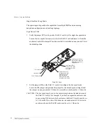
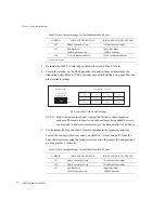
Set the jumper (JP4) on the Disk I/O card(s) to configure the bus speed mode.

Locate the JP4 jumper and position the jumper for the desired speed setting. Install 
the jumper on one pin only for 2 Gb mode or install it on both pins for 1 Gb mode.

CAUTION:

The bus speed must be set to the same setting between the disk drives and 
the Disk I/O card(s). For example, if you have an expansion enclosure and 
you are using 2 Gb drives in both enclosures, the Disk I/O cards must be set 
to 2 Gb mode. If you have 2Gb drives in one enclosure and 1 Gb drives in 
another enclosure, the Disk IO cards must be set to 1 Gb mode.

3

Re-install the Disk I/O card. Repeat this for the second Disk IO card.

4

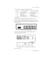
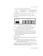
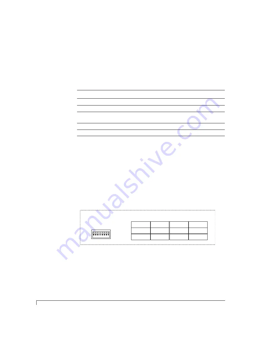
Locate the switches on the SES Controller card and set them as indicated in the 
illustration below. Refer to “SES Controller Card Switch Settings” on page 34 for the 
other available settings.

SES Controller Card Switch Settings

5

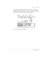
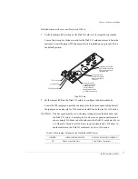
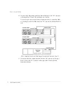
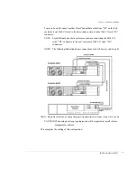
Connect a Fibre Channel data cable from one host HBA port to the “D1” connector 
on the upper Disk I/O card.

6

Connect a second Fibre Channel data cable from another host HBA port or a second 
host HBA to the “D2” connector on the upper Disk I/O card.

Disk I/O Card Jumper Settings for the OmniStor 4000F Series

JUMPER

INSTALLED BOTH PINS

INSTALLED ONE PIN (OFFSET)

JP1

Wahoo Controllers Only

* Non-Wahoo Controllers

JP2

Wahoo Controllers Only

* Non-Wahoo Controllers

JP3

Split Bus Mode
JBOD Enclosures Only

* Single Bus Mode

JBOD Enclosures

JP4

1 Gb/sec Bus Speed Mode

* 2 Gb/sec Bus Speed Mode

* indicates default setting

A
D
2

A
D
0

1 2

3

4 5 6 7

8

A
D
1

S

P
0

S

P
1

B
D
R

D

L
Y

R
M
T

ID 0

S

lot 1

S

lot 2

S

lot 4

S

lot 5

S

lot 7

S

lot 

8

S

lot 10

S

lot 11

ID 2

ID 1

ID 

3

S

lot 

3

S

lot 6

S

lot 

9

S

lot 12

ID 

8

ID 

9

ID 4

ID 6

ID 5

ID 7

ID 10

ID 11

UP (1)

DOWN (0)

ID

s

 A

ss

igned to Di

s

S

lot

s

S

witch 

S

etting

s

Summary of Contents for OMNISTOR 4000f SERIES

Page 1: ......

Page 2: ......

Page 3: ...ems Inc All Rights Reserved Rackable Systems Inc 1933 Milmont Ave Milpitas CA 95035 http www rackable com Rackable Systems and OmniStor are trademarks of Rackable Systems Inc The names of actual companies and products mentioned herein may be the trademarks of their respective owners Agency Notes WARNING Drives and controller adapter cards described in this manual should only be installed in UL lis...

Page 4: ......

Page 5: ...us Indicator LEDs 16 Drive LEDs 16 Audible Alarm 17 2 Topologies and Operating Modes 19 Operating Mode Overview 19 JBOD Topology 20 Fibre Channel Media Types 22 3 Setup and Installation 23 Overview 23 Storage System Detailed Installation 24 Installing the Storage System Enclosure into the Rack Cabinet 24 Installing the Storage System into the Tower Stand 27 Completing the Installation 29 Before Yo...

Page 6: ...sure Fan Speed Control 66 5 Troubleshooting 69 General Enclosure Problems 69 Common Fibre Loop Bus Problems 70 Common Problems and Interpreting the LEDs 71 Terminal and COM Port Problems 72 Problems During Bootup 72 6 Maintenance 73 Removing the Front Bezel 73 Replacing the Cooling Fans 75 Replacing an AC Power Supply 77 Replacing a DC Power Supply 79 Replacing a Disk Drive 81 Replacing the Disk I...

Page 7: ...nnector Pinout 94 C Regulatory Information 95 Compliance Information Statement 95 FCC Class A Radio Frequency Interference Statement 96 Class A Taiwanese Statement 97 Class A Japanese Statement 97 CE Notice 97 Power Cord Selection 98 Index 99 ...

Page 8: ...Table of Contents iv ...

Page 9: ...nclosure supports up to twelve hot pluggable 1 inch high Fibre Channel disk drives in a 2U 3 47 inch form factor Full component redundancy is provided through a hot pluggable cooling fan module which contains dual in line fans that will continue to provide adequate cooling should one fan fail dual Disk IO cards and an N 1 power system with dual independent power supplies Each power supply is a hot...

Page 10: ...module It also includes configuration software DB 9 null modem cable and a rackmount rail kit þ This user s guide is your complete documentation to set up the storage system hardware add components cable the storage system components replace parts and diagnose repair your system Refer to Managing and Monitoring on page 55 for enclosure management operations For details on software configuration re...

Page 11: ...u choose View Unused Drives n Code font will indicate literal text used in examples n Italic code font indicates a replaceable or variable item in code n Italic text indicates the item that is selected or chosen n Key strokes are enclosed in brackets e g Esc K or Enter Customer Care You will find warranty customer service and technical support on the Rackable Systems web site Refer to http www rac...

Page 12: ...n Hot pluggable disk drives 12 per enclosure n Hot pluggable cooling fan module n Dual redundant AC power supplies n Optional Dual redundant DC power supplies n Dual 2 Gb sec disk side channels for high performance failure resilient paths to the drives Disk channels are optimized with full duplex operations n SES Enclosure management includes onboard environmental monitoring n Designed to fit stan...

Page 13: ... onboard monitoring systems The Components section identifies and gives a complete description of each major component The Monitoring section describes the enclosure s LEDs and the manner in which normal and abnormal conditions are presented OmniStor 4000F Storage System Tower Model Rack Mount Model ...

Page 14: ...O D2 Tx Tx Tx Fib re Di sk IO LR C P N 08 9 96 31 80 01 A W Re v 1 IN ST AL L JU MP ER S 1 2 FO R HA RD WA RE FA ILU RE DE TE CT AD D JU MP ER FO R 1G OP ER AT IO N JP 2 JP 2 JP 3 JP 1 AD D JU MP ER FO R SP LIT BU S MO DE D1 DISK I O D2 Tx Tx Tx F i b r e D i s k I O L R C P N 0 8 9 9 6 3 1 8 0 0 1 A W R e v 1 I N S T A L L J U M P E R S 1 2 F O R H A R D W A R E F A I L U R E D E T E C T A D D J ...

Page 15: ...the SES controller The SES controller manages the signals to the front panel through a smart interconnect Power is applied to the front bezel through the interface edge connector where a control circuit monitors the bezel for proper connection When the bezel is properly installed and power is applied to the enclosure the bezel is immediately energized Refer to Control and Monitoring on page 15 for...

Page 16: ...ront bezels Power On LED will also be illuminated indicating that power has been applied Each power supply also incorporates an amber general Fault LED If the power supply is installed and power is not applied to the power supply or the power supply cooling fan fails the Fault LED will illuminate along with an audible alarm The front bezels Power Supply Status LED will illuminate green when both p...

Page 17: ...ibed on the previous page with the exception of the power cord bale NOTE The DC system must be installed in a restricted access location in accordance with intent of the National Electrical Code A restricted access location is defined as an area intended only for qualified or trained personnel only Access should be controlled by key lock or access card Each power supply has a special cable connect...

Page 18: ...n the power supply when the output power rating exceeds 110 to 130 of maximum rated output current DC Supply and Ground You DC supply and ground conductor must meet the following requirements n Suitable conductor material copper only n Power supply connections through the input connectors 12AWG 48V 48V Return Ground to the power supply n System ground conductor 8 AWG n Cable insulation rating mini...

Page 19: ... 5 minutes with the cooling fan module removed Cooling Fan Module The enclosure has temperature sensors in two different areas the drive bay and the power supplies There are several steps the storage system performs to prevent component damage due to over temperature conditions If the drive bay area reaches a temperature of 50 C 122 F an audible alarm will sound the front panel Fan Status LED will...

Page 20: ...ing to the illustration on the preceding page two jumpers are provided on the fan module printed circuit board to override the software control of the fan speeds This hardware setting routes full power voltage to the fans for maximum operational speed which is greater than the maximum speed set by the automatic software control This configuration is normally used when fan speed noises are not an i...

Page 21: ...0 and external monitoring software such as StorView SES Controller Card At power up the SES processors will read the switch settings and execute a self test The cards firmware also contains software functions for enclosure monitoring and management This firmware is flash upgradeable using the SES RS 232 Service port located on the card face plate Refer to Uploading SES Controller Card Firmware on ...

Page 22: ...ll configure a series of pre determined range of device IDs Refer to the table below Disk Device ID Switch Settings For example if the setting for switches 1 through 3 are Down the device ID addresses for drive slots 1 12 would be 0 11 respectively Slot 1 Slot 4 Slot 7 Slot 10 Slot 3 Slot 6 Slot 9 Slot 12 Slot 2 Slot 5 Slot 8 Slot 11 Viewed from the front of the enclosure SES RS 232 A D 0 A D 1 1 ...

Page 23: ...hed to all of the drive slot start signals Switch 7 controls the Start_1 signal Delay Spin up and switch 8 controls the Start_2 signal Remote Spin up The table below describes the function of each switch DL Switch 7 RM Switch 8 Drive Spin up Mode Down 0 Down 0 Drive motor spins up at DC power on Down 0 Up 1 Drive motor spins up only on SCSI start commands Up 1 Down 0 Drive motor spins up after a d...

Page 24: ...y are designed to support NCITS T11 Fibre Channel compliant devices at speeds of 1 0625 Gb per sec or 2 125 Gb per second The speed is set through a hardware jumper JP4 located on the Disk IO card Setting the jumper on both pins will enable the 1 Gb sec mode likewise offsetting the jumper will enable the 2 Gb sec mode An LED on the card will illuminate to indicate the 2 Gb mode Disk I O Card D1 DI...

Page 25: ... upper Loop A and lower Loop B NOTE The jumpers JP1 and JP2 are unique for a specific model controller They are not applicable to this model and therefore both jumpers should be installed in the offset position or installed on one pin only It s important to understand which card slot addresses which drive port loop when making JBOD cabling connections to the host or daisy chained enclosures NOTE T...

Page 26: ... A D 0 A D 1 A D 2 S P 1 S P 2 B D R D L Y R M T SES D1 DIS K IO D2 Tx Tx Tx Fib re Dis k IO LR C P N 08 9 96 31 80 01 A W Re v 1 INS TA LL JU MP ER S 1 2 FO R HA RD WA RE FA ILU RE DE TE CT AD D JU MP ER FO R 1G OP ER AT ION JP 2 JP 2 JP 3 JP 1 AD D JU MP ER FO R SP LIT BU S MO DE D1 DISK IO D2 Tx Tx Tx F i b r e D i s k I O L R C P N 0 8 9 9 6 3 1 8 0 0 1 A W R ev 1 I N S TA L L JU M P E R S 1 2...

Page 27: ...mation is also communicated to external monitoring software Refer to VT 100 Interface Enclosure Monitoring on page 60 for complete details Front Bezel LEDs and Reset Button Identification The OmniStor 4000F incorporates a One Touch Annunciation Configuration Display which provides LED readout of the current switch configuration fan control and Disk I O speed mode and Disk I O card presence Refer t...

Page 28: ...Supply Status The Power Supply Status LED indicates the condition of the power supplies The LED will illuminate steady green when both power supplies are functioning normally and will change to amber if one of the power supply should fail or is turned off Fan Status The Fan Status LED indicates the condition of the cooling fans The LED will illuminate green when both fans are functioning normally ...

Page 29: ... alarm will sound when any of the enclosure s component status changes to an abnormal state To silence the alarm press the Alarm Reset button located on the front bezel The corresponding alarm s LED will remain illuminated until the condition returns to a normal state ...

Page 30: ...Chapter 1 Getting Started Audible Alarm 18 ...

Page 31: ...ogy It can be configured as a split bus dual loop storage solution or a single bus dual loop storage solution Operating Mode Overview JBOD allows you to configure the enclosure s drives to support a variety of host environments topologies In this operating mode the enclosure can be configured as a split bus six drives each dual loop FC AL solution or a single bus twelve drives or more dual loop FC...

Page 32: ... are connected to this configuration will determine whether the operating mode provides a dual loop and or a redundant path solution to the drives If Port 1 and Port 2 of the HBA are connected to Loop A and Loop B respectively volume management software is required to manage the mirror drives that appear to the operating system Drives are seen on the bus as follows n D1 Upper card addresses drive ...

Page 33: ...t on one pin to enable this option When enabled it also activates the internal hubs and provides a continuous FC loop to the drives This is the default configuration NOTE This single bus dual loop configuration is used for the daisy chained enclosures that expand the drive channels in a RAID configuration Single Bus Dual Loop Operating Mode Logical View Depending on how the host or hosts are conne...

Page 34: ...nclosure However both copper and optical media types are supported Copper provides a lower cost solution although it is not as reliable as Fibre optic cable It serves distances up to 10 meters between nodes Fibre optical is a higher cost solution however it provides a more reliable media and supports distances up to 300 meters between nodes ...

Page 35: ...ly review this information and perform the steps of procedures in each applicable section in the order in which they are presented This will ensure a smooth and trouble free installation The installation is divided into two sections The first section describes installing the enclosure s into the rack cabinet or installing the enclosure chassis into the tower stand The second section of this chapte...

Page 36: ... into the rack cabinet The enclosure chassis could be damaged during installation due to the added unbalanced weight of the power supplies 2 Remove the storage system from its shipping carton and inspect for obvious damage a Remove and open the accessory kit Inside you will find the power cable s serial communication cable and the documentation software CD Also you will find a QuickStart instructi...

Page 37: ...ear to the vertical member using the supplied screws and nuts NOTE Ensure the enclosure is level S E S C O N T R O L L E R P A R T N U M B E R 0 8 9 9 6 3 2 2 0 0 1 A R T W O R K R E V I S I O N 1 JP 1 JP 2 RS 232 A D 0 A D 1 A D 2 S P 1 S P 2 B D R D L Y R M T SES D1 DIS K I O D2 Tx Tx Tx Fib re Dis k IO LR C P N 08 9 96 31 80 01 A W Re v 1 INS TA LL JU MP ER S 1 2 FO R HA RD WA RE FA ILU RE DE T...

Page 38: ...ttaching the Chassis Ears 8 Re install the power supplies Slide each power supply into its empty bay and ensure it seats completely and that the release latch resets 9 Continue now with Completing the Installation on page 29 Front Rack Vertical Member Mounting Screw Chassis Ear Nut Nut Mounting Screw ...

Page 39: ...from the enclosure Repeat for the other power supply 3 Remove the cooling fan module Place your finger in the handle and slide the release latch to the right with your thumb while pulling it from the enclosure 4 Remove the tower stand case from its shipping carton and inspect for obvious damage 5 Locate the accessory kit in the tower shipping carton It should contain eight 10 32 pan head screws an...

Page 40: ...tion Installing the Storage System into the Tower Stand 28 Inserting and Securing the Chassis 11 Re install the cooling fan module Slide it into its open bay and ensure it seats Mounting Screws Mounting Screws Mounting Screw A B C ...

Page 41: ...isk drives a Remove each drive from its anti static protective packaging Inspect for obvious damage b Install each disk drive into a drive slot by aligning the drive carrier rails with the grooves in the drive bay wall Because the drive carrier has tension clips ensure a snug fit it requires some force to seat the drive Repeat this step to populate all the required drive slots Installing Disk Driv...

Page 42: ...Disk I O cards The transceiver can only be installed one way Note the orientation and ensure you are inserting them correctly NOTE Refer to the illustration on the following page b Push the transceiver fully into the SFP cage so that it completely seats The transceiver protrudes approximately 1 2 inch from the face plate of the card when it is fully seated c Optical Transceiver Remove the dust cov...

Page 43: ...s highly recommended S E S C O N T R O L L E R P A R T N U M B E R 0 8 9 9 6 3 2 2 0 0 1 A R T W O R K R E V I S I O N 1 JP 1 JP 2 RS 232 A D 0 A D 1 A D 2 S P 1 S P 2 B D R D L Y R M T SES D1 DIS K I O P2 Tx Tx Tx Fib re Dis k IO LR C P N 08 9 96 31 80 01 A W Re v 1 INS TA LL JU MP ER S 1 2 FO R HA RD WA RE FA ILU RE DE TE CT AD D JU MP ER FO R 1G OP ER AT IO N JP 2 JP 2 JP 3 JP 1 AD D JU MP ER F...

Page 44: ...er Supply system refer to the following procedures to properly connect the cables 1 Plug the connector into the power supply it is keyed to install only one way 2 Connect the two Red pair wires to the DC Feed 48VDC connection 3 Connect the two Green Yellow pair wires to the DC Feed ground connection 4 Connect the two Black pair wires to the DC Feed 48VDC connection Attaching the DC Cable 5 Repeat ...

Page 45: ...vided In the last section of this chapter are the steps to properly power on or power off your storage system Special Note for Microsoft Windows 2000 Installations At startup you will see the Found New Hardware Wizard appear Adriver is not required for the storage system a driver inf file is provided on the Software Documentation Disc which can be installed to satisfy this requirement Refer to the...

Page 46: ...ble it will assign a new ID Negotiated addressing occurs when a hard address or a previous address does not exist and it will then negotiate the bus for a new device ID The disadvantage of negotiated device IDs is that there is a potential liability of the device ID changing due to reconfiguration and therefore could cause potential problems The SES Controller card has a set of switches which conf...

Page 47: ...anges During the cabling and setup procedures in the next section specific switch settings are provided DL Switch 7 RM Switch 8 Drive Spin up Mode Down Down Drive motor spins up at DC power on Down Up Drive motor spins up only on device start commands Ranges Switch IDs 0 11 IDs 16 27 IDs 32 43 IDs 48 59 IDs 64 75 IDs 80 91 IDs 96 107 IDs 112 123 Down Down Down Down Down Down Down Down Up Down Down...

Page 48: ...e following pages for the specific configuration that you will be completing Refer to Split Bus Dual Loop Mode on page 37 Refer to Single Bus Dual Loop Mode on page 44 Up Down Drive motor spins up after a delay of 12 may vary depending on drive type seconds times the numeric device ID setting of the associated drive Up Up Drive motor will not spin up Default setting for proper operation DL Switch ...

Page 49: ...rive slots on Loop A and connector D2 provides the connection to the right side drive six drive slots on Loop A 1 Set the jumper JP3 on the Disk I O card to enable split bus operations Loosen the two captive fastener screws for the Disk I O card and remove it from the enclosure Locate the JP3 jumper and position the jumper onto both pins The default position is the offset position Disk I O Card D1...

Page 50: ...llustration below Refer to SES Controller Card Switch Settings on page 34 for the other available settings SES Controller Card Switch Settings 5 Connect a Fibre Channel data cable from one host HBA port to the D1 connector on the upper Disk I O card 6 Connect a second Fibre Channel data cable from another host HBA port or a second host HBA to the D2 connector on the upper Disk I O card Disk I O Ca...

Page 51: ...will cause the drive IDs to change since the host HBA ID address is assigned before the device IDs For example if the ID range 0 11 is selected choose a hard address ID for the host HBA between the range of 12 through 15 If a second enclosure is added to expand the drive channels most likely it will have ID range 16 27 assigned to its devices Using this method prevents an ID conflict 8 Power on yo...

Page 52: ...OmniStor 4000F Series JUMPER INSTALLED BOTH PINS INSTALLED ONE PIN OFFSET JP1 Wahoo Controllers Only Non Wahoo Controllers JP2 Wahoo Controllers Only Non Wahoo Controllers JP3 Split Bus Mode JBOD Enclosures Only Single Bus Mode JBOD Enclosures JP4 1 Gb sec Bus Speed Mode 2 Gb sec Bus Speed Mode indicates default setting D1 DISK I O D2 OK OK 2G F i b re D i s k I O L R C P N 0 8 9 9 6 3 1 8 0 0 1 A...

Page 53: ...Controller Card Switch Settings 5 Connect a Fibre Channel data cable from the Host 1 first HBA port to the D1 connector on the upper Disk I O card 6 Connect a second Fibre Channel data cable from the Host 1 second HBA port to the D2 connector on the upper Disk I O card 7 Connect a third Fibre Channel data cable from a Host 2 first HBA port to the D1 connector on the lower Disk I O card 8 Connect a...

Page 54: ...ed on the host HBA most likely there will be a conflict This will cause the drive IDs to change since the host HBA ID address is assigned before the device IDs For example if the ID range 0 11 is selected choose a hard address ID for the host HBA between the range of 12 through 15 If a second enclosure is added to expand the drive channels most likely it will have an ID range of 16 27 10 Power on ...

Page 55: ...ling configurations remember that the upper Disk I O card communicates on Loop A and the lower Disk IO card on Loop B The D1 connection provides access to the left six drive slots 7 12 and the D2 accesses the right six drive slots 1 6 JBOD Split Bus Dual Loop Cabling Diagram Using a Switch Hub This completes the cabling of this configuration ...

Page 56: ... be set to the same setting between the disk drives and the Disk I O card s For example if you have an expansion enclosure and you are using 2 Gb drives in both enclosures the Disk I O cards must be set to 2 Gb mode If you have 2Gb drives in one enclosure and 1 Gb drives in another enclosure the Disk IO cards must be set to 1 Gb mode D1 DISK I O D2 OK OK 2G F i b re D i s k I O L R C P N 0 8 9 9 6...

Page 57: ...op Cabling Diagram with a Single Hosts 6 Set the Host HBA ID Disk I O Card Jumper Settings for the OmniStor 4000F Series JUMPER INSTALLED BOTH PINS INSTALLED ONE PIN OFFSET JP1 Wahoo Controllers Only Non Wahoo Controllers JP2 Wahoo Controllers Only Non Wahoo Controllers JP3 Split Bus Mode JBOD Enclosures Only Single Bus Mode JBOD Enclosures JP4 1 Gb sec Bus Speed Mode 2 Gb sec Bus Speed Mode indic...

Page 58: ...ill cause the drive IDs to change since the host HBA ID address is assigned before the device IDs For example if the ID range 0 11 is selected choose a hard address ID for the host HBA between the range of 12 through 15 If a second enclosure is added to expand the drive channels most likely it will have an ID range of 16 27 7 Power on your system refer to Powering On the Storage System on page 53 ...

Page 59: ...b drives in both enclosures the Disk I O cards must be set to 2 Gb mode If you have 2Gb drives in one enclosure and 1 Gb drives in another enclosure the Disk IO cards must be set to 1 Gb mode Disk I O Card Jumper Settings for the OmniStor 4000F Series JUMPER INSTALLED BOTH PINS INSTALLED ONE PIN OFFSET JP1 Wahoo Controllers Only Non Wahoo Controllers D1 DISK I O D2 OK OK 2G F i b re D i s k I O L ...

Page 60: ...sure using the fastener screws Locate the jumper JP4 and position it on both pins for 1 Gb mode JP2 Wahoo Controllers Only Non Wahoo Controllers JP3 Split Bus Mode JBOD Enclosures Only Single Bus Mode JBOD Enclosures JP4 1 Gb sec Bus Speed Mode 2 Gb sec Bus Speed Mode indicates default setting Disk I O Card Jumper Settings for the OmniStor 4000F Series JUMPER INSTALLED BOTH PINS INSTALLED ONE PIN ...

Page 61: ...ID address for the host HBA s that will not conflict with any of the drive ID ranges NOTE If soft addressing is used on the host HBA most likely there will be a conflict This will cause the drive IDs to change since the host HBA ID address is assigned before the device IDs For example if the ID range 0 11 is selected choose a hard address ID for the host HBA between the range of 12 through 15 If a...

Page 62: ... Loop B connect another Fibre Channel data cable to a second Host HBA or a second port on the first HBA then to the D1 connector on the lower Disk I O card JBOD Single Bus Dual Loop Cabling Diagram Using Multiple Enclosures Loop A 11 Connect another Fibre Channel data cable from the D2 connector on the upper Disk I O card to the D1 connector on the upper Disk I O card in the first daisy chain encl...

Page 63: ...ional daisy chain enclosures continue connecting the Disk I O cards D2 connector to the next enclosure s Disk I O cards D1 connectors NOTE The following illustration depicts connections for both Loop A and Loop B JBOD Single Bus Dual Loop Cabling Diagram Using Multiple Enclosures Loop A Loop B CAUTION When using dual loop topologies you will be required to install volume management software This c...

Page 64: ...tem provides you with this ability to meet your expanding data storage requirements The upgrade process is relatively easy remove the blank plate and install two Host IO cards and one or two RAID Controller s Set the enclosure SES Controller card switch settings and Host IO card jumpers and switches for the new configuration topology Then cable the storage system enclosures as indicated in the ins...

Page 65: ...ar of the enclosure s 2 Press each power supply switch to its On position Repeat this step for each of the attached storage system enclosure s All enclosures will perform a power on self test during their initial start 3 Next power on the host computer s which are connected to the storage system Powering Off the Storage System NOTE If you are planning to completely shut down the entire system powe...

Page 66: ...Chapter 3 Setup and Installation Powering Off the Storage System 54 ...

Page 67: ...sure monitoring components You should monitor your storage system regularly to ensure that the disk drives and enclosure components are working properly The front bezel LEDs provide monitoring information for the enclosure components fan status disk drive status and array monitoring Enclosure Component Monitoring This section covers notifications provided by the front bezel LEDs and a detailed exp...

Page 68: ...illuminate steady green when both power supplies are functioning normally and will change to amber if one of the power supplies should fail or be turned off A failed power supply can be identified by the illumination of the amber Fault LED located on the individual power supply Fan Status The Fan Status LED indicates the condition of the cooling fans The LED will illuminate green when both fans ar...

Page 69: ...ive LEDs This LED will illuminate steady green when a drive is present in the slot and powered on If a drive is not present the LED will be off Drive Activity LEDs There are twelve Drive Activity LEDs These LEDs will flash indicating a specific drive is being accessed either during read or write activity The Drive Activity LED is the right LED of each pair of Drive LEDs RESET ALARM Drive LEDs Alar...

Page 70: ...l Drive LEDs that is drive activity information and drive fault failure notifications when the front bezel is removed Drive Carrier LitePipes Audible Alarm An audible alarm will sound when any of the enclosure s component condition changes to an abnormal state To silence the alarm press the Alarm Reset button located on the front bezel The corresponding LED will remain illuminated until the condit...

Page 71: ...pper Disk I O Card Present Press and Hold to display settings Upper CNTRL Present Lower Disk I O Card Present Fan Control Enabled SES Switch AD0 Position SES Switch AD1 Position SES Switch AD2 Position One Touch Annunciation Configuration Display LED On Up Position LED Off Down Position LED On Up Position LED Off Down Position LED On Up Position LED Off Down Position LED On Auto Control Enabled LE...

Page 72: ...ng program 1 Connect one end of the null modem serial cable to the SES RS 232 Service port located on the rear panel of the enclosure RS 232 Service Port Connection NOTE The cable is a female to female DB 9 null modem serial cable and is included with the storage system Refer to Null Modem Cable Specifications on page 167 for cable specifications 2 Connect the other end of the cable to either a ho...

Page 73: ... screen provides a status list of the internal components such as disk drives in a specific slot temperature of the thermal sensors cooling fan status power supply status and statistics on enclosure up time Enclosure Environment Status Screen NOTE System degradation will occur if the display is left in the Show Enclosure Environment Status mode After you have viewed the information press the Esc k...

Page 74: ... for both SES processors This option allows the user to scroll back through the buffer data or select the Transfer Capture Text to save the buffer captures to a text file SES Commands Debug Screen NOTE Options 2 SES Commands Debug 3 Environment Testing Menu and 4 Cycle Test are available for use by manufacturers and OEMs during developement They are not intended as normal user s options ...

Page 75: ...vice Port Connection NOTE The cable is a female to female DB 9 null modem serial cable and is included with the storage system Refer to Null Modem Cable Specifications on page 167 for cable specifications 2 Connect the other end of the cable to either a host system s RS 232 serial communication port or a VT 100 type terminal 3 On the host system run a terminal emulation program or start the VT 100...

Page 76: ...reen 6 Select option 5 Firmware Upload by pressing the 5 key Upload Firmware Screen 7 Press the u key lower case to start the upload Using the mouse click on the pull down menu Transfers and select Send Send File Screen 8 Click the browse button and locate the new Firmware file and click Send The firmware file name will be similar to k305 s3r extension ...

Page 77: ...been completed The upload does not overwrite the firmware during the upload process it writes the new code into unused EEPROM space until completed then erases the flash and re programs the new firmware code to the EEPROM active region If you elect to stop an upload in progress ensure that the stop abort command was completed by typing Control X at the cursor Xmodem Transfer Screen 9 Verify the ne...

Page 78: ... for more efficient management of the cooling fans and a whisper mode fan operation for noise sensitive environments where it significantly reduces the noise created by the cooling fans running constantly at full speed Under normal conditions it is not necessary to run the cooling fans at full speed 1 At the cursor type Control E The Enclosure Terminal Utility menu will appear Enclosure Terminal U...

Page 79: ...processor fails Manual Override A manual override of the fan speed control is available for special circumstance environments Referring to the illustration on the following page two jumpers are provided on the fan module printed circuit board to override the firmware control of the fan speeds This hardware setting provides full voltage to the fans for maximum operational speed which is greater tha...

Page 80: ... and JP2 are by default are offset which enables the use of the automatic fan speed control The jumper JP1 controls Fan 0 and JP2 controls Fan 1 Placing the included jumper on both pins of each jumper will override the automatic setting and set the fans to maximum power ...

Page 81: ...ty power cord Faulty power supply Verify that the power cord is properly connected to the power module If the enclosure is plugged into a three hole grounded outlet verify that power to the outlet has not been interrupted This can be accomplished by testing the outlet with a known working appliance like a lamp Be sure that the power switch is in the On position labeled with an I Replace the power ...

Page 82: ...speed mode as the Disk I O Cards It is not recommended to use the auto setting of the HBA speed mode Manually set the speed mode All disk devices must be 2 Gb drives if the 2 Gb mode is selected on the DIsk I O Card and Host HBA If 1 Gb mode is selected the disk devices can be 2 Gb or 1 Gb drives Faulty Transceiver 1 Verify that the transceiver are functional in the Disk I O card and the Host HBA ...

Page 83: ...ply and turn it on Verify that proper AC power is available to the power supplies If the enclosure is plugged into a three hole grounded outlet verify if power to the outlet has been interrupted This can be accomplished by testing the outlet with a known working appliance like a lamp Fan Status LED is illuminated steady amber Failed cooling fan Replace cooling fan canister Fan Status LED is flashi...

Page 84: ...ser s guide 2 Power down the enclosure 3 For Hyper Terminal a Select the File menu and choose Properties b Click the Configure button c Choose 9600 and click OK Nothing is displayed on the terminal emulator screen The probable cause of this problem is a bad RS 232 cable connection or swapped transmit receive lines If the cable is properly connected ensure that the cable is a null modem type Screen...

Page 85: ...res to replace individual components as well as the entire storage system enclosure Removing the Front Bezel 1 Using a Phillips screwdriver unlock the two front bezel fasteners Unlocking the Front Bezel Rotate the fasteners counterclockwise one quarter turn to unlock Reset Alarm ...

Page 86: ...Chapter 6 Maintenance Removing the Front Bezel 74 2 Grasp and pull the front bezel from the enclosure Refer to the illustration below Removing the Front Bezel Reset Alarm ...

Page 87: ...ATI ON JP2 JP2 JP3 JP1 AD D JU MP ER FO R SP LIT BU S MO DE D1 DISK I O D2 Tx Tx Tx F i b r e D i s k I O L R C P N 0 8 9 9 6 3 1 8 0 0 1 A W R ev 1 I N S TA L L JU M P E R S 1 2 F O R H A R D W A R E FA I L U R E D E T E C T A D D JU M P E R F O R 1 G O P E R AT I O N JP 2 JP 2 JP 3 JP 1 A D D JU M P E R F O R S P L I T B U S M O D E S E S C O N T R O L L E R P A R T N U M B E R 0 8 9 9 6 3 2 2 0...

Page 88: ...gn the cooling fan module with the opening fan bay and push the module into the enclosure until it completely seats The latch will reset when the module is completely seated The front bezel Fan Status LED will return to a normal state green 4 Using the packaging material from the replacement cooling fan module re package and return the failed cooling fan module per your RMA instructions ...

Page 89: ... BU S MO DE D1 DISK I O D2 Tx Tx Tx F i b r e D i s k I O L R C P N 0 8 9 9 6 3 1 8 0 0 1 A W R e v 1 I N S TA L L JU M P E R S 1 2 F O R H A R D W A R E F A I L U R E D E T E C T A D D JU M P E R F O R 1 G O P E R A T I O N JP 2 JP 2 JP 3 JP 1 A D D JU M P E R F O R S P L I T B U S M O D E S E S C O N T R O L L E R P A R T N U M B E R 0 8 9 9 6 3 2 2 0 0 1 A R T W O R K R E V I S I O N 1 J P 1 J ...

Page 90: ...er supply by sliding it into its open bay and ensuring it seats completely and the release latch resets 6 Re connect the AC power cord Insert the power cord into the AC power cord module and secure it with the power cord bale 7 Turn the On Off switch to the On position on the replacement power supply NOTE The front bezel Power Supply Status LED will return to a normal state steady green 8 Using th...

Page 91: ... BU S MO DE D1 DISK I O D2 Tx Tx Tx F i b re D i s k I O L R C P N 0 8 9 9 6 3 1 8 0 0 1 A W R e v 1 I N S T A L L J U M P E R S 1 2 F O R H A R D W A R E F A I L U R E D E T E C T A D D J U M P E R F O R 1 G O P E R A T I O N J P 2 J P 2 J P 3 J P 1 A D D J U M P E R F O R S P L I T B U S M O D E S E S C O N T R O L L E R P A R T N U M B E R 0 8 9 9 6 3 2 2 0 0 1 A R T W O R K R E V I S I O N 1 J...

Page 92: ...pply by sliding it into its open bay and ensuring it seats completely and the release latch resets 6 Re connect the DC power cable Insert the power cable connector into the DC power cable module It secures when the connector s latches reset 7 Turn the On Off switch to the On position on the replacement power supply NOTE The front bezel Power Supply Status LED will return to a normal state steady g...

Page 93: ...e drives are hot swappable Be careful of the P factor effect when removing a disk drive which is the twisting of the drive in your hand as a result of the spinning disk Allow the drive to completely spin down before removing it Do this by pulling the drive slightly from its locked position and allowing it to spin down then remove the drive 1 Identify the failed disk drive using the Drive Status LE...

Page 94: ...al 5 Install the replacement disk drive a Align the drive carrier with the rail grooves in the drive bay b Ensure that the drive seats completely The drive carrier tension clips ensure that the disk drive fits very tight so it requires some force to push the drive into its bay Installing the Disk Drive 6 Re install and secure the front bezel Using a Phillips screwdriver rotate the fasteners clockw...

Page 95: ...pivoting mechanism Use the edge of your finger tip or the finger nail to engage the ejector and pull towards you This will release the transceiver b The type B model uses a similar mechanism to the type A except it rotates about a pivot point Use the edge of your finger tip or the finger nail to engage the ejector and pull towards you This will release the transceiver c The type C model uses a pul...

Page 96: ...n the two captive fastener screws Do not overtighten the screws 12 Insert the transceiver s into each of the SFP cages located on the Disk I O card S E S C O N T R O L L E R P A R T N U M B E R 0 8 9 9 6 3 2 2 0 0 1 A R T W O R K R E V I S I O N 1 JP 1 JP 2 RS 232 A D 0 A D 1 A D 2 S P 1 S P 2 B D R D L Y R M T SES D1 DIS K I O D2 Tx Tx Tx Fib re Dis k IO LR C P N 08 9 96 31 80 01 A W Re v 1 INS T...

Page 97: ...t completely seats The transceiver protrudes approximately 1 2 inch from the Disk I O card face plate when it s completely seated 13 Remove the dust covers just prior to inserting the FC data cables Store them in a safe place 14 Re connect the Fibre Channel data cables to the replacement card 15 Using the packaging materials from the replacement card repackage the failed card and return it per you...

Page 98: ...sure 5 Remove the new replacement card from the shipping container and inspect for obvious damage Save the packaging materials SES Controller Card Switches 6 Set the switch settings on the replacement card to match those of the faulty card 7 Insert the replacement card by aligning it into the rail guides and push the card until it fully seats Tighten the two captive fastener screws Do not overtigh...

Page 99: ...tation of the location of the data cables prior to disconnecting or removing these items To facilitate correct installation you may want to tag the cables appropriately 3 Disconnect the FC data cables and power cords cables from the faulty storage enclosure 4 Remove the front bezel 5 Remove each power supply 6 Remove the cooling fan module 7 Remove the SES Controller card and Disk I O cards NOTE B...

Page 100: ...10 Re install the SES Controller card and Disk I O cards 11 Re install the power supplies 12 Re install the cooling fan module 13 Reconnect the Fibre Channel data cables and power cords Refer to the notations made prior to removing the cables for their proper connection location 14 Power on the storage enclosure s and then the host computer s Refer to Powering Off the Storage System on page 53 15 ...

Page 101: ...ency Dimensions Rack Mount Unit HxWxD Dimensions Tower Unit HxWxD 3 47 x 17 65 x 20 25 20 00 x 8 00 x 21 50 Weight Rack Mount Unit w 2 power supplies Weight Tower Unit w 2 power supplies 38 55 lbs w o drives 58 00 lbs with twelve drives 48 05 lbs w o drives 67 50 lbs with twelve drives Altitude 200 to 10 000 feet Number of Drives Supported 12 per enclosure Host Interface FC AL Fibre Channel Arbitr...

Page 102: ...0950 00 UL 60950 3rd Edition CB IEC 60950 Edition 3 CE Compliance EMC 89 336 EEC EMC Directive EN55024 Shock Operating Non Operating 1 0 G 2 50 ms 20 0 G 2 20ms Vibration Operating Non Operating 5 500 Hz 0 25 G pk to pk 5 500 Hz 1 0 G pk to pk Technical Specifications for the OmniStor 4000F Storage System ...

Page 103: ...ller using a standard null modem cable Through this RS 232 service port you can use a VT 100 terminal or emulation such as HyperTerminal to access the onboard firmware for monitoring and maintenance and firmware update operations The SES Controller Service Port is located on the SES Controller Card and is labeled RS 232 SES Controller Card Service Port Pin Signals 1 1 NC 2 Rx 3 Tx 4 NC 5 Gnd 6 NC ...

Page 104: ...l Modem Cable This cable is a DB 9 female to DB 9 female null modem type and is used to connect a VT 100 terminal or emulation terminal to the SES Controller Card Service port DB 9 to DB 9 Null Modem Cable Pin Signals 1 2 3 4 5 6 7 8 9 1 2 3 4 5 6 7 8 9 ...

Page 105: ...rcuit which provides TTL logic high output when an unusable input signal is detected SFP Optical Transceiver Models The SFP transceiver is a Class 1 Laser safety compliant device and conforms to Class 1 eye safety standards CAUTION Do not look into the laser light beam for any extended period of time Dust covers are provided to protect the transceivers optics We highly recommend using the dust cov...

Page 106: ...pplies and is used to connect to a DC power feed system NOTE Use only the DC power cables provided with the system Before connecting the cable to the source be sure the wiring has the correct pin out as indicated below The connectors are Molex type plug and female socket DC Cable Wiring Signals Top Left 48 VDC Top Right 48 VDC Middle Left 48 VDC Middle Right 48 VDC Lower Left GND Lower Right GND P...

Page 107: ... System Enclosure Model Number OmniStor 4000S to which this declaration relates is in conformity with the Title 47 of the US Code of Federal Regulations Part 15 covering Class A personal computers and peripherals Operation is subject to the following two conditions 1 This device may not cause harmful interference and 2 This device must accept any interference received including interference that m...

Page 108: ...e the user will be required to correct the interference at his own expense Rackable Systems is not responsible for any interference caused by unauthorized modifications to this equipment It is the user s responsibility to correct such interference You are also warned that any changes to this certified device will void your legal right to operate it WARNING Drives and controller adapter cards descr...

Page 109: ...se Statement Class A Japanese Statement CE Notice Marking by the CE symbol indicates compliance of the device to directives of the European Community A Declaration of Conformity in accordance with the above standards has been made and is available from Rackable Systems upon request ...

Page 110: ...molded on tandem blade grounding type attachment plug rated 15A 250V configuration 6 15P at the other end For 230 Volt Operation Europe Use a cord set marked HAR consisting of a H05VV F cord that has a minimum 0 75 square mm diameter conductors provided with an IEC 320 receptacle and a male plug for the country of installation rated 6A 250V NOTE The enclosure automatically selects the proper setti...

Page 111: ...g Fan Module 7 D DC Cable Wiring Signals 94 DC Power Supply 5 DC Power Supply Connector Pinout 94 Device ID 10 Device ID Ranges 35 Dimensions 89 Disk I O Card 12 Replacing 83 Disk I O Link LED is not illuminated 70 Drive Activity LEDs 57 Drive ID Settings 10 Drive LEDs 16 56 Drive Spin up 35 Drive Status LED is illuminated amber 71 Drive Status LEDs 57 Drives Supported Number of 89 E EMC 90 EMI 89...

Page 112: ... Powering On Storage System 53 Power On LED 16 56 R Rack Cabinet Installation 24 RAID Controller Enclosure General Problems 69 Relative Humidity 89 Removing the Front Bezel 73 Replacing Enclosure 87 Replacing a DC Power Supply 79 Replacing a Disk Drive 81 Replacing an AC Power Supply 77 Replacing the Cooling Fans 75 Replacing the Disk I O Card 83 Replacing the SES Controller Card 86 RS 232 Service...

Reviews: