Maintenance and Performance Checks 5-17
The troubleshooting procedure should also be initiated whenever
the synthesizer fails to perform either completely or partially. It is
also required to troubleshoot the Model 3152 whenever the
instrument fails to fully comply with its published specifications.
The information given in the following does not intend to replace
full scale troubleshooting, but merely to direct the Service
Technician to the area were the source of the trouble is located.
Main Board
Circuit Checkout
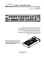
The Model 3152 is made of two boards. The large board (Part
Number 7100-2370) is the main board. There is a smaller board
mounted on the main board with three connectors (Part Number
7100-2360). This smaller board is called the “engine board”. The
following checks are made on the main board. To gain access to
components below the engine board, it may be necessary to
remove this board entirely. To do so, remove the three screws that
tie the engine board to the main board, grasp the engine board
from both sides and pull away from the main board.
Power Supply
Checkout
It is suggested that the first step in troubleshooting the Model 3152
would be to check the power supply rails. If the various supply
voltages within the instrument are not within the required limits,
troubleshooting the remaining circuits can be very difficult.
The supply voltages are supplied to the Model 3152 through the
backplane. In case of a "dead short" between one of the supplies
to the common ground, disconnect the entire supply section from
the remaining circuitry, and then determine whether the problem
is in the power supply or in the remaining circuits.
A few preliminary checks could help here. First remove the Model
3152 from the VXIbus chassis. Turn on the VXIbus chassis and
verify that the supply voltages are available directly on the
backplane sockets. Check the following supplies: +24V, -24V,
+12V, -12V, +5V, and -5.2V. Check the ripple on these lines using
an oscilloscope.
Plug an extension card into one of the slots and plug the Model
3152 into the extension card. Turn the chassis power on and
repeat the supply voltage tests as above. If one of the voltages is
missing or not within the specified range, it is possible that one of
the supply lines is shorted inside the Model 3152. Remove the filter
chokes L12 and L13 if there are problems on the +24V or -24V
lines; remove L8 or L9 if there are problems on the +5V or -5.2V
lines, or remove L10 or L11 if there are problems on the +12V or
-12V lines.
CPU and VXI ASIC
Checkout
The most important section to be verified after power supply
checkout is the CPU and the VXI ASIC section with its various
clocks, address, data lines, and chip select serial data
communication components. Problems with the digital part could
cause erratic operation or erroneous response to word serial
commands.
Summary of Contents for 3152
Page 16: ...Getting Started 1 7 Figure 1 1 Segment 1 Sin x x Waveform Figure 1 2 Segment 2 Sine Waveform...
Page 25: ...Configuring The Instrument 2 6 This page was intentionally left blank...
Page 63: ...Using The Instrument 3 38 This page was intentionally left blank...
Page 80: ...SCPI Command Reference 4 17 Figure 4 1 SCPI Status Registers...
Page 121: ...Specifications A 12 This page was intentionally left blank...