


68
EM1500 Configuration
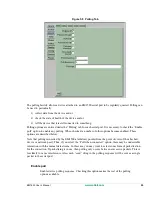
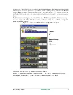
5.1.11.1 Auxiliary I/O and Relay Tray
The first tray applies to the auxiliary
I/Os and the relay. This is labelled as
“AUX.” All of the controls are buttons.
The button color indicates whether the
control is currently an input or output, and its state on bootup. Green indicates an input, and orange indi-
cates an output.
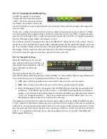
For the relay, a bright color indicates the it is closed, a dark color indicates it is open. For In0-2, a bright
color indicates the state on bootup is high, a dark color indicates it is low. For Out0-1, a bright color indi-
cates the state on bootup is Hi-Z, a dark color indicates it is pulled low. For PF0-4, a bright color indicates
the state on bootup is high, a dark color indicates it is low.
If you click on a button, a message will be sent to the EM1500 to change the state of the control. If it can
change the control, the EM1500 responds with a confirmation message that updates the display. For exam-
ple, if you click the “Relay” button, the relay will toggle and the button will change color. The button may
also change color in response to other events that cause the control to change state.
The AUX buttons all toggle the state of the specified I/O line or the relay.
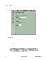
5.1.11.2 Serial Port Trays
Below the AUX tray are the trays for
each serial port. Each serial port tray con-
tains mainly status information, with but-
tons to manually override some
functions.
The status indicators show the state of
each of the modem control lines that are actually available, as well as whether data is being transmitted or
received. On the top row are 3 indicators and 3 buttons. The indicators are:
•
TxD
: shows whether any data has been transmitted to the serial port since last update.
•
RxD
: shows whether any data has been received from the serial port since last update.
•
Flow
: if illuminated (yellow), this indicates that the EM1500 cannot currently transmit data to the
serial device. Note that the opposite flow control, i.e., the EM1500 stalling the device from trans-
mitting, is not currently shown in the display. Note that for the RS485 port, this indicator is labelled
“Txen” for “transmitter enabled” — this is the equivalent function for the RS485 port, since it is
half-duplex and does not have flow control in the usual sense.
The indicators below the first row show the status of each modem control line. SER1 and SER2 also have
a “NoC” indicator. This indicates whether any device is attached to the serial port. If no device is attached
(or the device is not powered up) then there will be zero volts on each of the serial port input lines. In this
case, the serial port driver detects that there is no connection. Otherwise, at least one of the lines will have
at least +/-3 V applied, in which case the no connection indicator (NoC) is turned off. Only SER1 and
SER2 support this feature.
Summary of Contents for EM1500
Page 14: ...10 www rabbit com Introduction...
Page 22: ...18 www rabbit com Getting Started...
Page 76: ...72 www rabbit com EM1500 Configuration...
Page 90: ...86 www rabbit com EM1500 Specifications...
Page 104: ...100 www rabbit com Serial and TCP Protocols...
Page 118: ...114 www rabbit com EM1500 FAQ...


