EM1500 User’s Manual
23
4.2 Back Panel of EM1500
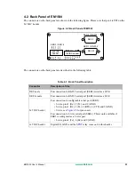
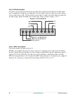
The connectors on the back panel are shown in the following figure. Please note that pin 1 is PF2 on the
2x5 IDC header.
Figure 4.2 Back Panel of EM1500
The connectors on the back panel are described in the following table.
Table 4.3 Back Panel Description
Connector
Description of Use
DE9, male
For connection to RS-232 serial port (SER1) wired as a DTE.
DE9, female
For connection to RS-232 serial port (SER2) wired as a DCE.
2x5 IDC header
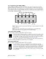
For connection to configurable serial port (SER3):
• 3-wire, pins 3 (Rx), 5 (Tx), and 9 (GND)
• 5-wire, pins 3 (Rx), 5 (Tx), 4 (RTS), 6 (CTS) and 9 (GND)
• 9-wire, see
for pins used.
For connection to 3-wire serial port (SER4). This is only available if
SER3 is configured as a 3-wire port.
• 3-wire, pins 4 (Tx), 6 (Rx) and 9 (GND).
1x9 IDC header
Digital I/O, GND, and the
relay come out on this header.
IN0
IN2
GND
IN1
NO
NC
OUT0
OUT1
PF1
COM
PF3
PF4
PF2
RLY
IN
OUT
PF0
GND
2x5 IDC
header
1x9 IDC header
DE9 F
DE9 M
SER 2 / RS-232
SER 1 / RS-232
Rx4
Tx4
Tx3
Rx3
SER 3 / SER 4
Summary of Contents for EM1500
Page 14: ...10 www rabbit com Introduction...
Page 22: ...18 www rabbit com Getting Started...
Page 76: ...72 www rabbit com EM1500 Configuration...
Page 90: ...86 www rabbit com EM1500 Specifications...
Page 104: ...100 www rabbit com Serial and TCP Protocols...
Page 118: ...114 www rabbit com EM1500 FAQ...

