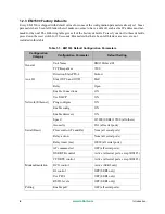


16
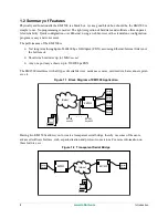
Getting Started
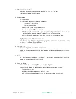
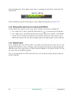
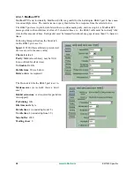
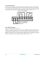
In the status/debug area of the program window, there is a grouping of controls for the auxiliary I/O that
looks like this:
Figure 2.3 AUX Tray
Detailed information about the status/debug area of the configuration program is in
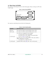
2.3.2 Wiring the Demo Board to the Selected EM1500
You must follow these steps before you can use the Demo Board to test the relay and digital I/O:
1. Use a single wire to cK from the Demo Board to V
input
(screw terminal) on the EM1500.
2. Use a single wire to connect GND from the Demo Board to GND (screw terminal) on the EM1500.
3. Connect the 9-wire assembly with plug that came with the Tool Kit to the 9-pin connector on the
EM1500. The3 pins for the relay, plus the 2 digital outputs and 3 digital inputs are all available here.
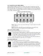
2.3.3 Digital Output
To test the digital output, wire OUT0 and OUT1 to any LED on the Demo Board. To locate the wires com-
ing from OUT0 and OUT1, do one of 2 things: look at the unit itself, then read the text on the back panel
labelling the pins on the 9-pin connector; or look at the pinout diagram by selecting the “Pinouts” tab, then
the “9-pin” tab in the stand-alone program.
Now you can click on OUT0 or OUT1 in the AUX tray to see the LED on the Demo Board to which it is
connected, light up.
Summary of Contents for EM1500
Page 14: ...10 www rabbit com Introduction...
Page 22: ...18 www rabbit com Getting Started...
Page 76: ...72 www rabbit com EM1500 Configuration...
Page 90: ...86 www rabbit com EM1500 Specifications...
Page 104: ...100 www rabbit com Serial and TCP Protocols...
Page 118: ...114 www rabbit com EM1500 FAQ...


