Instruction Book
98
9828 0934 73
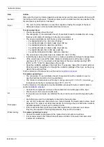
Electrical
connection
•
Check that the primary side connections of transformer (T1) correspond with the
supply voltage.
•
See the section
Electric cable size and fuses
for the recommended fuses and cable
size of the supply cables.
•
Check that the electrical installation corresponds to the local codes. The dryer must be
earthed and protected against short circuits by fuses of the inert type in all phases.
•
An isolating switch must be installed near the dryer.
•
The fix speed units are provided with a phase sequence relay. When the dryer does not
start, switch off the voltage and reverse two incoming electric lines.
•
All pipes should be installed stress-free to the dryer unit.
•
All pipes should be installed so that there is no obstruction accessing the unit through the
removable panels.
4.4 Electrical cable size and fuses
Important
Local regulations remain applicable if they are stricter than the values proposed.
For 50 Hz dryers, the settings of the main fuses below are according to Directive 73/23/EEC
(low-voltage directive) EN60204, 83/336/EC electromagnetic compatibility. The cable size is
valid for cable PVC 70 ˚C (158 ˚F) at an ambient temperature of 40 ˚C (104 ˚F).
For 60 Hz dryers, the settings of the main fuses below are according to CSA standards C22.2
Nos. 0; 0.4; 0.5; 0.12; 14; 68 and UL508. The cable size is valid for cable 90 ˚C (194 ˚F) at an
ambient temperature of 40 ˚C (104 ˚F).
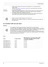
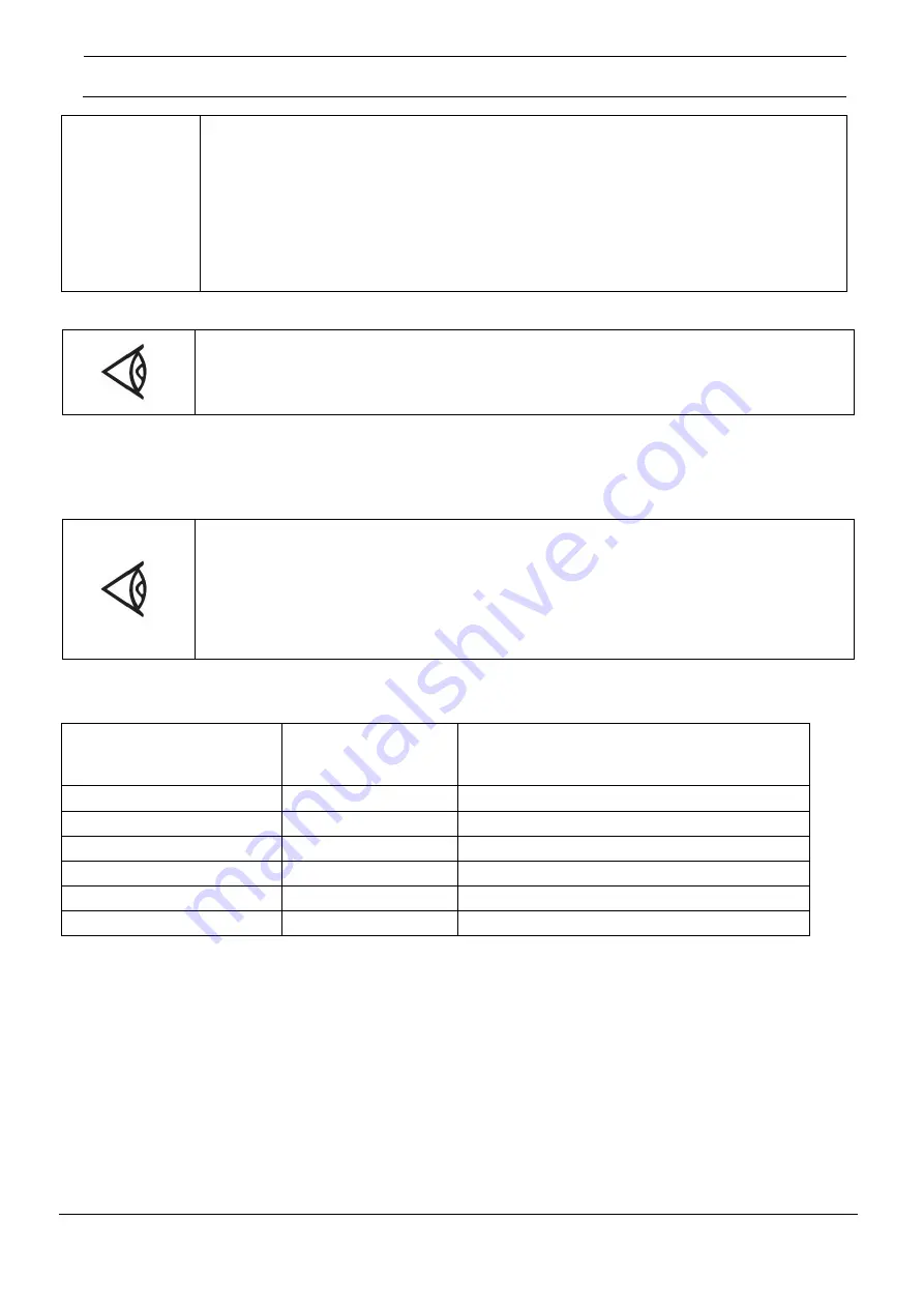
Fuses
Dryer
Supply voltage
Maximum fuses, recommended type: (CSA)
Class HRC Form II/(UL) Class K5 or RK5
(customer's installation)
QED-650 (
ES 310
)
400 V
3 x 20 A
QED-850 (
ES 410
)
400 V
3 x 20 A
QED-1050 (
ES 510
)
400 V
3 x 20 A
QED-650 (
ES 310
)
460 V
3 x 20 A
QED-850 (
ES 410
)
460 V
3 x 20 A
QED-1050 (
ES 510
)
460 V
3 x 25 A

