5. LCD assembly & Electronics
Original Prusa MINI+ kit assembly
89
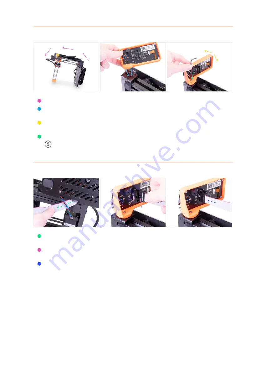
STEP 3
Mounting the LCD
First, carefully tilt the printer on its side. See the picture.
Place the LCD into the LCD holder. There is a notch, which fits inside the printed
part on the printer.
The design allows you to tilt the LCD into multiple positions. You can do it now or
later.
Use the M3x20 screw to connect both parts together.
Pro tip: if you find it difficult to tighten the screw, turn over the Allen key and
use the short side.
STEP 4
Connecting the LCD
Carefully remove the free end of the LCD cable from the box with the electronics
and guide the cable between the Y-axis motor cable and the extrusion.
Connect the cable to the board on the LCD. Mind the correct orientation of the
connector. Use the notch as a guide.
Insert the connector in the socket on the board. Make sure it is all the way in.
Summary of Contents for Original Prusa MINI
Page 5: ...Original Prusa MINI kit assembly 5 1 Introduction ...
Page 14: ...14 Original Prusa MINI kit assembly 2 YZ axis assembly ...
Page 47: ...Original Prusa MINI kit assembly 47 3 X axis Extruder assembly ...
Page 73: ...Original Prusa MINI kit assembly 73 4 Print head Heatbed assembly ...
Page 87: ...Original Prusa MINI kit assembly 87 5 LCD assembly Electronics ...
Page 100: ...100 Original Prusa MINI kit assembly 6 Spool holder assembly ...
Page 105: ...Original Prusa MINI kit assembly 105 7 Preflight check ...
Page 109: ...109 Notes ...
Page 110: ...110 ...
Page 111: ...111 Notes ...
Page 112: ...112 ...
Page 113: ...113 Notes ...
Page 114: ...114 ...
Page 115: ...115 Notes ...
Page 116: ...116 ...


