4. Print head & Heatbed assembly
Original Prusa MINI+ kit assembly
85
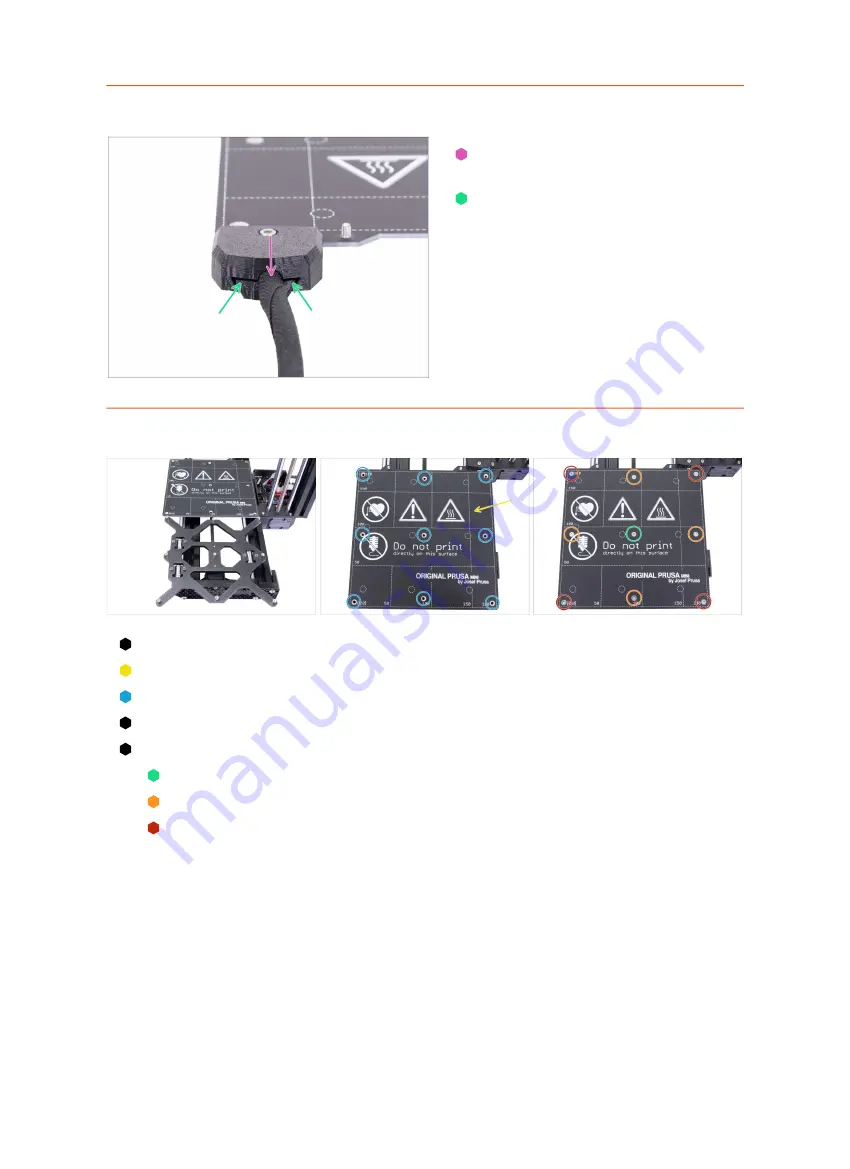
STEP 25
Covering the heatbed cables
Slightly pull out the sleeve to make
sure it is properly inserted.
Make sure there is no big gap
between both covers.
STEP 26
Mounting the heatbed assembly
Push the Y-carriage to the front and place the Heatbed behind.
Place the heatbed on the Y-carriage.
Align all 9 holes on the heatbed with the heatbed spacers.
Insert the M3x4b screws in the holes.
DON'T fully tighten the screws.
After all screws are in place, use the torx key to tighten them in the following order:
Center screw
First four screws (edges)
Last four screws (corners)
Summary of Contents for Original Prusa MINI
Page 5: ...Original Prusa MINI kit assembly 5 1 Introduction ...
Page 14: ...14 Original Prusa MINI kit assembly 2 YZ axis assembly ...
Page 47: ...Original Prusa MINI kit assembly 47 3 X axis Extruder assembly ...
Page 73: ...Original Prusa MINI kit assembly 73 4 Print head Heatbed assembly ...
Page 87: ...Original Prusa MINI kit assembly 87 5 LCD assembly Electronics ...
Page 100: ...100 Original Prusa MINI kit assembly 6 Spool holder assembly ...
Page 105: ...Original Prusa MINI kit assembly 105 7 Preflight check ...
Page 109: ...109 Notes ...
Page 110: ...110 ...
Page 111: ...111 Notes ...
Page 112: ...112 ...
Page 113: ...113 Notes ...
Page 114: ...114 ...
Page 115: ...115 Notes ...
Page 116: ...116 ...


