Chapter 3 Hardware Configuration
PA-3222 SERIES USER MANUAL
Page: 3-10
3.5.5
USB Ports (USB0, USB1, USB2, USB3, USB5)
Port Name:
USB0, USB1, USB2, USB3, USB5
Description:
USB Type A Ports
•
USB0-3: Rear I/O
•
USB5: Side I/O
PIN ASSIGNMENT
1
+5V (Max. current: 0.5A)
2
D-
3
D+
4
GND
Note:
The USB0 port is provided with Standby power 5V.
The other USB ports are without standby power.
3.5.6
LAN Port (LAN)
Port Name:
LAN
Description:
LAN RJ-45 Port (rear IO)
PIN ASSIGNMENT
PIN ASSIGNMENT
1
MDIP0
5
MDIP2
2
MDIN0
6
MDIN2
3
MDIP1
7
MDIP3
4
MDIN1
8
MDIN3
LAN LED Status
There are LAN LED indicators for LAN on the rear panel of the system. By
observing their status, you can know the status of the Ethernet connection.
RB Ver.
LAN LED
Indicator
Color
Status
Description
Left Side
LED
Orange
Blink
Giga LAN connection is activated.
Green
Blink
10/100Mbps LAN connection is activated.
Right Side
LED
Green
On
LAN switch/hub connected.
USB0/
USB1/
USB2/
USB3/
USB5
LAN
Summary of Contents for PA-3222
Page 1: ...USER MANUAL PA 3222 10 1 POS Terminal Powered by Intel Celeron J1900 Quad Core PA 3222 M1...
Page 11: ...viii Configuring WatchDog Timer B 10 Flash BIOS Update B 13...
Page 24: ...Chapter 2 Getting Started PA 3222 SERIES USER MANUAL Page 2 10 2 3 6 Side View 147 75...
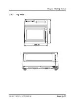
Page 26: ...Chapter 2 Getting Started PA 3222 SERIES USER MANUAL Page 2 12 2 4 3 Top View...
Page 163: ...Chapter 4 Software Utilities PA 3222 SERIES USER MANUAL Page 4 78...
Page 221: ...Appendix A System Diagrams PA 3222 SERIES USER MANUAL Page A 4...
Page 247: ...Appendix B Technical Summary PA 3222 SERIES USER MANUAL Page B 14...

