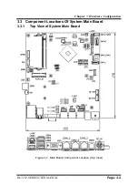
Chapter 3 Hardware Configuration
PA-3222 SERIES USER MANUAL
Page: 3-3
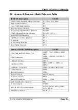
3.2 Jumper & Connector Quick Reference Table
JUMPER Description
NAME
COM2/COM3 Port Pin9 Voltage Selection
JP_COM2, JP_COM3
BIOS Update Selection
JP1
Clear CMOS Data Selection
JP2
Panel Resolution Selection
JP5, JP6
Touch Panel Signal Interface Selection
JP8, JP9
COM2, i-Button Function Selection
JP10, JP11, JP12
Mini PCIE USB Selection
JP13
Cash Drawer Control Selection
JP15
LVDS Link
JP16
LVDS Voltage Selection
JP17
Panel Enable Selection
JP20
System CONNECTOR Description
NAME
COM Ports and Cash Drawer Port
COM2, COM3, COM1, COM4,
DRW1
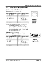
COM Connectors
COM1_1, COM2_1, COM3_1,
COM4_1
i-Button Connector
I-BUT
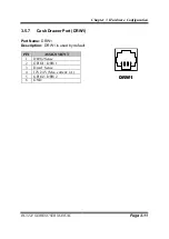
Cash Drawer Ports
DRW1 (DRW1-1, DRW1-2),
DRW2
USB Ports / Connectors
USB0-3, USB5, USB6, USB7
LED Connector
LED1
Speaker Connector
SPK1_1
Power Connector
DC12V, DC24V
Inverter Connector
INV1
Reserved Connectors
SPK2_1, GPIO1
MSR / Card Reader Connector
PS2
LVDS Connector
LVDS1
SATA & SATA Power Connectors
SATA1, SATA2, SATA_PWR1,
SATA_PWR2
Mini-PCIe Connector
M_PCI_E1
Summary of Contents for PA-3222
Page 1: ...USER MANUAL PA 3222 10 1 POS Terminal Powered by Intel Celeron J1900 Quad Core PA 3222 M1...
Page 11: ...viii Configuring WatchDog Timer B 10 Flash BIOS Update B 13...
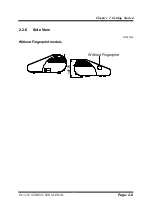
Page 24: ...Chapter 2 Getting Started PA 3222 SERIES USER MANUAL Page 2 10 2 3 6 Side View 147 75...
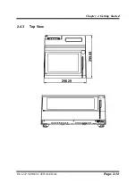
Page 26: ...Chapter 2 Getting Started PA 3222 SERIES USER MANUAL Page 2 12 2 4 3 Top View...
Page 163: ...Chapter 4 Software Utilities PA 3222 SERIES USER MANUAL Page 4 78...
Page 221: ...Appendix A System Diagrams PA 3222 SERIES USER MANUAL Page A 4...
Page 247: ...Appendix B Technical Summary PA 3222 SERIES USER MANUAL Page B 14...


