PLX3x Series ♦ Multi-Protocol Gateways
EIP Protocol
User Manual
ProSoft Technology, Inc.
Page 59 of 215
January 25, 2018
5
Add a new module under the
Generic EtherNet Bridge
and add a CIP
Connection (
CIP-MODULE
). Here is where you specify the parameters for
the I/O connection. The input and output sizes need to match the input and
output sizes configured in PCB. The
A
DDRESS
field value represents the
connection number in PCB. By default all of the connections have 248 Input
words, 248 Output words, and 0 Configuration words. Set the Comm format
to Data type INT, and set the Assembly instances to be "1" for input, "2" for
output, and "4" for configuration.
6
Add and configure a CIP Connection for each I/O connection.
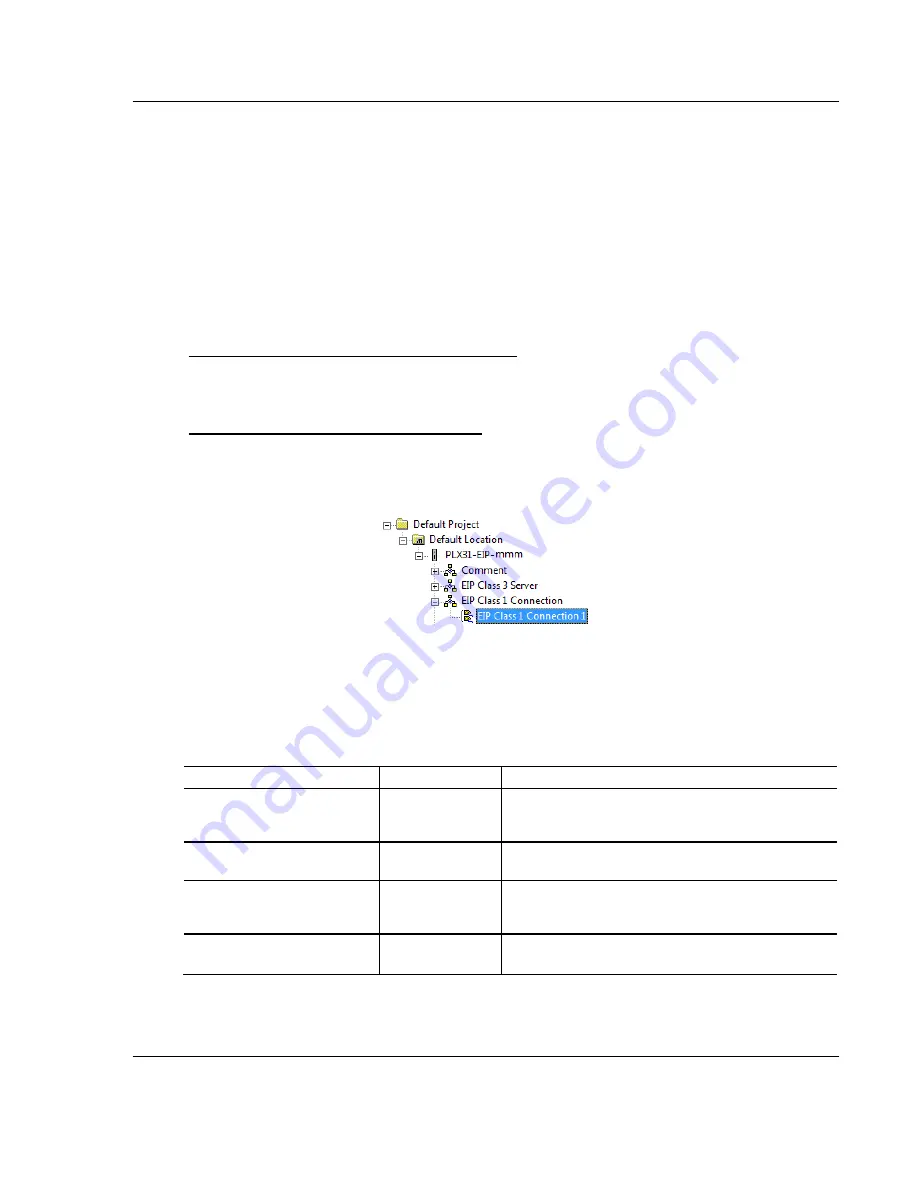
Configuring EIP Class 1 Connections in PCB
After you have created the PLX3x module in RSLogix 5000, you must configure
the connections in the module.
To configure Class 1 connections in PCB
1
In
ProSoft Configuration Builder
, click the
[+]
next to the gateway, then click
the
[+]
next to
EIP Class 1 Connection [x]
. The value of [x] depends on the
number of ports on your PLX3x gateway (1 to 4).
2
Double-click the
EIP Class 1 Connection [x]
to display the
Edit - EIP Class 1
Connection [x]
dialog box.
3
In the dialog box, click a parameter and then enter a value for the parameter.
There are four configurable parameters for each I/O connection in ProSoft
Configuration Builder.
Parameter
Value Range
Description
Input Data Address
0 to 3999
Specifies the starting address within the gateway’s
virtual database for data transferred from the gateway
to the PLC.
Input Size
0 to 248
Specifies the number of Integers being transferred to
the PLC's input image (248 integers max).
Output Data Address
0 to 3999
Specifies the starting address within the gateway’s
virtual database for data transferred from the PLC to
the gateway.
Output Size
0 to 248
Specifies the number of integers being transferred to
the PLC's output image (248 integers max).


