Chapter 5 Function parameter
55
Code
Parameter name
Setting range
Factory
default
Change
revoked, the inverter will continue wobbulate at the current frequency.
21: Wobbulate reset: the set frequency of inverter gets back to the center frequency.
22: Torque control prohibited: the Inverter switches from torque control mode to speed
control mode.
23: Temporarily clear frequency change setting:the frequency value set by "UP" and
"DOWN" keyboard can be cleared when the terminal is connected so that for the set
frequency gets back to the frequency set by command channel, return the frequency
value set by frequency change setting again when the terminal is disconnected.
24: Stop DC braking: during the process of deceleration stop, when the terminal is
connected, the inverter will immediately perform DC braking, the braking state is
determined by F3.07 ~ F3.09.
25: Reserved
F1.06
Terminal control operation
mode
Two-wire type control 1
0
0
★
Two-wire type control 2
1
Three-wire type control
1
2
Three-wire type control
2
3
This parameter defines four different modes to control inverter operation through
external terminals.
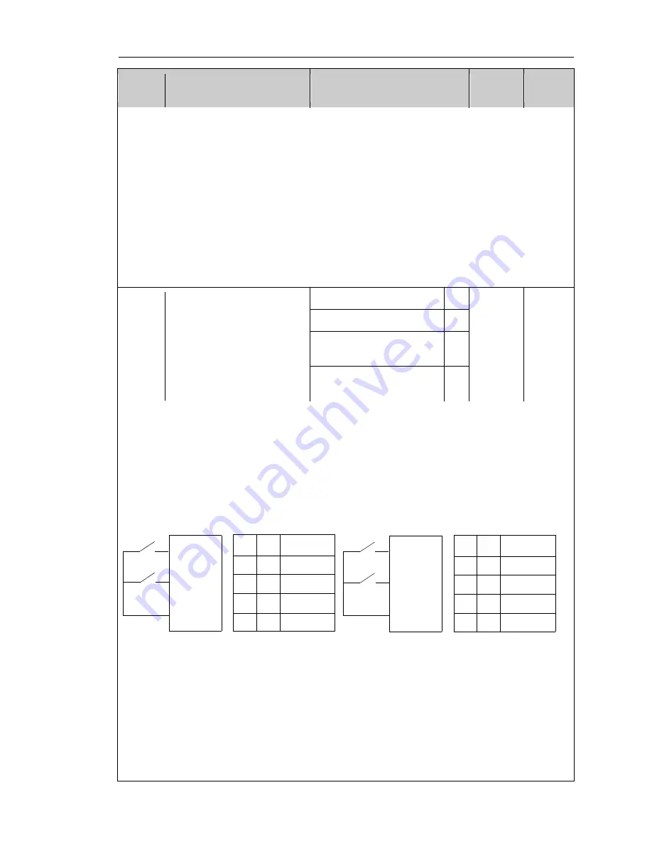
0: Two-wire type control 1
Combine ENABLE and direction. This mode is the most commonly used two-wire
mode. The forward and reverse running of motor is determined by the defined FWD,
REV terminal commands.
1: Two-wire type control 2
Separate ENABLE and direction. FWD defined by this mode is the enable terminals.
The direction is determined by the defined REV state.
K1 K2
Running
command
OFF
ON
OFF
OFF
OFF ON
ON ON
Stop
Forward run
Reverse run
Stop
K1
K2
FWD
REV
COM
In
v
er
te
r
K1 K2
Running
command
OFF
ON
OFF
OFF
OFF ON
ON ON
Stop
Forward run
Reverse run
Stop
K1
K2
FWD
REV
COM
In
v
er
te
r
Two-wire type control 1 (Combine ENABLE and direction) Two-wire type
control 2 (Separate ENABLE and direction)
2: Three-wire type control 1
In this mode, DIn is as the enable terminal, SB1 as level control is active; the running
command is controlled by the pulse rising edge of SB2 or SB3 so as to control forward
or reverse of the motor; the stop command is controlled by the switch SB1.
3: Three-wire type control 2
In this mode, DIn is as the enable terminal, SB1 as level control is active; the running
command is produced by FWD, SB2 as pulse edge control is active, the running
direction of motor is determined by REV, K1 as level control is active.
Inve
rt
er
Forward run


