Replacement of Parts - Page 44
PL5
P
L
6
P
L
9
P
L
1
0
P
L
4
P
L
1
P
L
8
P
L
7
P
L
3
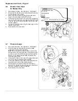
Test
Switch
Override
Normal
T.S/w
Control
Box
U
L
0
0
0
6
9
A
Fig. 52
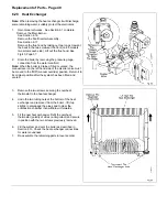
6.13
Test Switch
1.
Gain General Access - See Section 6.1, Paragraph 1.
2.
Disconnect the two electrical (spade) connectors from
the switch.
3.
Note which way the switch is fitted, compress the clips
on the switch body and push it out of the control box.
4.
Fit the new switch as shown with the spade connectors
to the bottom.
5.
Re-assemble in reverse order.
6.14
Overheat Cut-Off Device
1.
Gain General Access - See Section 6.1 complete.
2.
Disconnect the overheat thermostat leads.
3.
Remove the two screws securing the overheat
thermostat to the heat exchanger.
4.
Ensure that the mounting plate is clean, smear some
heat conductive grease onto the plate and secure the
new thermostat to the heat exchanger.
5.
Reconnect the leads (the polarity is not important).
6.
Re-assemble in reverse order.
Summary of Contents for Ultra 2
Page 6: ...Installation Requirements Page 6 Fig 1 ...
Page 7: ...Installation Requirements Page 7 Fig 2 ...
Page 9: ...Installation Requirements Page 9 ...
Page 37: ...Routine Maintenance Page 37 ...
Page 51: ...7 Wiring Diagrams Page 51 ...
Page 52: ...Wiring Diagrams Page 52 Ultra 2Dv ...
Page 53: ...Wiring Diagrams Page 53 Ultra 2 ...
Page 54: ...54 Fault Finding Part No 405 0522 8 Fault Finding Guide Page 54 ...
Page 55: ...Part No 405 0522 Fault Finding 55 Fault Finding Guide Page 55 ...
Page 56: ...56 Fault Finding Part No 405 0522 Fault Finding Guide Page 56 ...
Page 57: ...Part No 405 0522 Fault Finding 57 Fault Finding Guide Page 57 ...


